Nissan Cube. Manual - part 87


  Index      Nissan     Nissan Cube (2014 year) - Service and Repair Manual


Search            


Content   ..  85  86  87  88   ..


Nissan Cube. Manual - part 87


REAR DRUM BRAKE

BR-41

< REMOVAL AND INSTALLATION >

C

D

E

G

H

I

J

K

L

M

A

B

BR

N

O

P

• After installing the retainer ring, close the joint of retainer ring until securely closed.
• When disassembled adjuster, confirm the difference between left and right wheel for assemble.

• Apply PBC (Poly Butyl Cuprysil) silicone-based grease to the adjuster screw.
• Apply PBC (Poly Butyl Cuprysil) silicone-based grease to the mating faces between the adjuster and brake

shoe.

• Apply PBC (Poly Butyl Cuprysil) silicone-based grease to the mating faces between the back plate and

brake shoe.

• Shorten adjuster by rotating it.
• Install the brake shoe assembly so that it does damage the wheel cylinder.
• Check the component parts of brake shoe assembly are installed properly.
• Check the brake shoe sliding surface and brake drum inner surface for grease. Wipe it out any adheres to

the surfaces.

• Perform the air bleeding when removed or disassembled the wheel cylinder. Refer to 

BR-11, "Bleeding

Brake System"

.

• Never allow foreign matter (e.g. dust) and oils other than brake fluid to enter the reservoir tank.
• Adjust the brake shoe (parking brake lever stroke) after install and air bleeding. Refer to 

PB-3, "Inspection

and Adjustment"

.

Disassembly and Assembly

INFOID:0000000009949241

DISASSEMBLY

1.

Remove the boot from wheel cylinder. Refer to 

BR-39, "Exploded View"

.

2.

Remove the piston, piston cup and spring from wheel cylinder.

CAUTION:

Pull the piston out from the wheel cylinder to prevent the wheel cylinder inner wall from being
damaged.

3.

Remove boot and piston cup from piston.
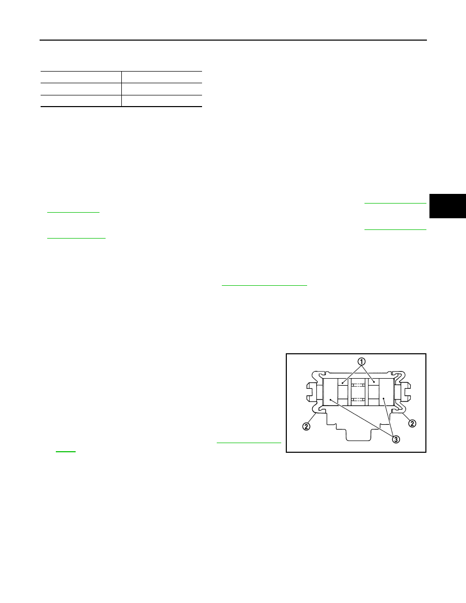
ASSEMBLY

1.

Apply polyglycol ether based lubricant to the piston cup (1) and
boot (2), and install them to piston (3).

CAUTION:

• Never mistake the direction. 
• Never reuse piston cup and boot.

2.

Apply brake fluid to piston and wheel cylinder inner wall, and
install spring and piston to wheel cylinder.

CAUTION:

Never damage the wheel cylinder inner wall.

3.

Install the boot to wheel cylinder. Refer to 

BR-39, "Exploded

View"

.

Inspection and Adjustment

INFOID:0000000009949242

INSPECTION AFTER REMOVAL

Check the following items and replace if necessary.
• Check the brake lining for excessive wear, damage, and peeling.
• Check the brake shoe sliding surface for excessive wear and damage.
• Check each spring for settling, excessive wear, damage, and rust.
• Check the adjuster for smoothness, and check it for excessive wear, damage, and rust.
• Check the back plate for damage, cracks, and deformation.
• Check the wheel cylinder for cracks, damage, and leakage of brake fluid.
• Visually check the brake drum for excessive wear, cracks, and damage with a pair of vernier calipers.
• Check the drum brake component parts for excessive wear, damage, and rust.

INSPECTION AFTER DISASSEMBLY

Adjuster

Direction

Left side

Left screw

Right side

Right screw

JPFIA0234ZZ

BR-42

< REMOVAL AND INSTALLATION >

REAR DRUM BRAKE

Check the following items and replace if necessary.
• Check the wheel cylinder inner wall for excessive wear, cracks, and damage.
• Check the piston for excessive wear and damage.

INSPECTION AFTER ASSEMBLY

Check that the piston moves smoothly.

INSPECTION AFTER INSTALLATION

1.

Check that the component parts of drum brake assembly are installed properly.

2.

Rotate the brake drum and check that there is no drag. Perform the following procedure if necessary.

a.

Remove the brake shoe. Refer to 

BR-39, "Exploded View"

.

b.

Push the piston.

CAUTION:

Push both side of the piston simultaneously.

c.

Install the brake shoe. Refer to 

BR-39, "Exploded View"

.

d.

Operate the brake pedal with a force of 196 N (20 kg, 44 lb) for 10 strokes or more.

e.

Check a drag of rear disc brake again. If any drag is found, disassemble the wheel cylinder. Refer to 

BR-

41, "Disassembly and Assembly"

.

ADJUSTMENT AFTER INSTALLATION

Adjust the brake shoe (parking brake lever stroke). Refer to 

PB-3, "Inspection and Adjustment"

.

SERVICE DATA AND SPECIFICATIONS (SDS)

BR-43

< SERVICE DATA AND SPECIFICATIONS (SDS) 

C

D

E

G

H

I

J

K

L

M

A

B

BR

N

O

P

SERVICE DATA AND SPECIFICATIONS (SDS)

SERVICE DATA AND SPECIFICATIONS (SDS)

General Specifications

INFOID:0000000009949243

Unit: mm (in)

Brake Pedal

INFOID:0000000009949244

Unit: mm (in)

Brake Booster

INFOID:0000000009949245

Unit: mm (in)

Front Disc Brake

INFOID:0000000009949246

Unit: mm (in)

Rear Drum Brake

INFOID:0000000009949247

Unit: mm (in)

Front brake

Cylinder bore diameter

57.2 (2.252)

Pad length 

×

 width 

×

 thickness

118.6 

×

 46.0 

×

 9.5 (4.67 

×

 1.811 

×

 0.374)

Rotor outer diameter 

×

 thickness

280 

×

 24.0 (11.02 

×

 0.945)

Rear brake 

Cylinder bore diameter

19.05 (0.750)

Lining length 

×

 width 

×

 thickness

218.6 

×

 35.0 

×

 4.0 (8.61 

×

 1.378 

×

 0.157)

Drum inner diameter

228.6 (9.00)

Master cylinder

Cylinder bore diameter

23.81 (15/16)

Control valve

Valve type

Electric brake force distribution

Brake booster

Diaphragm diameter

254 (10.00)

Recommended brake fluid

Refer to 

MA-10, "Fluids and Lubricants"

Item

Standard

Brake pedal height

M/T

162.3 – 172.3 (6.39 – 6.78)

CVT

172.4 – 182.4 (6.79 – 7.18)

Clearance among the brake pedal lever and the stop lamp switch threaded end

0.74 – 1.96 (0.0291 – 0.0772)

Clearance among the brake pedal bracket and the ASCD brake switch threaded end (with 
ASCD)

0.74 – 1.96 (0.0291 – 0.0772)

Brake pedal play

3 – 11 (0.12 – 0.43)

Depressed brake pedal height
[Depressing 490 N (50 kg, 110 lb) while turning the engine ON]

M/T

80 (3.15) or more 

CVT

85 (3.35) or more 

Item

Standard

Input rod length

158.5 – 159.5 (6.24 – 6.28)

Item

Limit

Brake pad

Wear thickness

2.0 (0.079)

Disc rotor

Wear thickness

22.0 (0.866)

Thickness variation (measured at 8 positions)

0.015 (0.0006)

Runout (with it attached to the vehicle)

0.035 (0.0014) 

Item

Limit

Brake lining

Wear thickness

1.5 (0.059)

Brake drum

Wear inner diameter

230.0 (9.06)

BRC-1

BRAKES

C

D

E

G

H

I

J

K

L

M

SECTION 

BRC

A

B

BRC

N

O

P

CONTENTS

BRAKE CONTROL SYSTEM

VDC/TCS/ABS

BASIC INSPECTION  ....................................

4

DIAGNOSIS AND REPAIR WORKFLOW  ..........

4

Work Flow  .................................................................

4

Diagnostic Work Sheet ..............................................

7

ADDITIONAL SERVICE WHEN REPLACING 
ABS ACTUATOR AND ELECTRIC UNIT 
(CONTROL UNIT)  ...............................................

8

Description ................................................................

8

Special Repair Requirement  .....................................

8

ADJUSTMENT OF STEERING ANGLE SEN-
SOR NEUTRAL POSITION  .................................

9

Description ................................................................

9

Special Repair Requirement  .....................................

9

SYSTEM DESCRIPTION  .............................

11

VDC ....................................................................

11

System Diagram ......................................................

11

System Description  .................................................

11

Component Parts Location ......................................

12

Component Description ...........................................

13

TCS .....................................................................

14

System Diagram ......................................................

14

System Description  .................................................

14

Component Parts Location ......................................

15

Component Description ...........................................

16

ABS ....................................................................

17

System Diagram ......................................................

17

System Description  .................................................

17

Component Parts Location ......................................

18

Component Description ...........................................

19

EBD ....................................................................

20

System Diagram ......................................................

20

System Description  .................................................

20

Component Parts Location  ......................................

21

Component Description  ...........................................

22

DIAGNOSIS SYSTEM [ABS ACTUATOR 
AND ELECTRIC UNIT (CONTROL UNIT)]  .......

23

CONSULT Function .................................................

23

DTC/CIRCUIT DIAGNOSIS  .........................

28

C1101, C1102, C1103, C1104 WHEEL SEN-
SOR ...................................................................

28

Description ...............................................................

28

DTC Logic ................................................................

28

Diagnosis Procedure  ...............................................

28

Special Repair Requirement ....................................

30

C1105, C1106, C1107, C1108 WHEEL SEN-
SOR ...................................................................

31

Description ...............................................................

31

DTC Logic ................................................................

31

Diagnosis Procedure  ...............................................

31

Special Repair Requirement ....................................

35

C1109 POWER AND GROUND SYSTEM  ........

36

Description ...............................................................

36

DTC Logic ................................................................

36

Diagnosis Procedure  ...............................................

36

Special Repair Requirement ....................................

37

C1110, C1153, C1170 ABS ACTUATOR AND 
ELECTRIC UNIT (CONTROL UNIT) .................

38

DTC Logic ................................................................

38

Diagnosis Procedure  ...............................................

38

Special Repair Requirement ....................................

38

C1111 ABS MOTOR, MOTOR RELAY SYS-
TEM ...................................................................

39

Description ...............................................................

39

DTC Logic ................................................................

39

Diagnosis Procedure  ...............................................

39

Special Repair Requirement ....................................

40


Content   ..  85  86  87  88   ..