Nissan Cube. Manual - part 71
BCS
BCM (BODY CONTROL MODULE)
BCS-133
< ECU DIAGNOSIS INFORMATION >
[WITHOUT INTELLIGENT KEY SYSTEM]
C
D
E
F
G
H
I
J
K
L
B
A
O
P
N
5
(G)
Ground
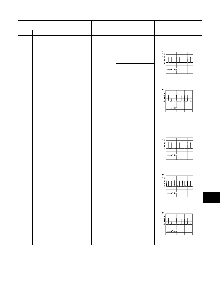
Combination switch
INPUT 2
Input
Combination
switch
All switch OFF
(Wiper intermittent dial 4)
0 V
Front washer switch
(Wiper intermittent dial 4)
1.0 V
Rear washer switch ON
(Wiper intermittent dial 4)
Any of the condition below
with all switch OFF
• Wiper intermittent dial 1
• Wiper intermittent dial 5
• Wiper intermittent dial 6
Rear wiper switch ON
(Wiper intermittent dial 4)
0.8 V
6
(L/R)
Ground
Combination switch
INPUT 1
Input
Combination
switch
All switch OFF
(Wiper intermittent dial 4)
0 V
Front wiper switch HI
(Wiper intermittent dial 4)
1.0 V
Rear wiper switch INT
(Wiper intermittent dial 4)
Wiper intermittent dial 3
(All switch OFF)
Any of the condition below
with all switch OFF
• Wiper intermittent dial 1
• Wiper intermittent dial 2
1.9 V
Any of the condition below
with all switch OFF
• Wiper intermittent dial 6
• Wiper intermittent dial 7
0.8 V
Terminal No.
(Wire color)
Description
Condition
Value
(Approx.)
Signal name
Input/
Output
+
−
PKIB4958J
PKIB4956J
PKIB4958J
PKIB4952J
PKIB4956J