Nissan Cube. Manual - part 40


  Index      Nissan     Nissan Cube (2014 year) - Service and Repair Manual


Search            


Content   ..  38  39  40  41   ..


Nissan Cube. Manual - part 40


BCS

BODY CONTROL SYSTEM

BCS-9

< SYSTEM DESCRIPTION >

[WITH INTELLIGENT KEY SYSTEM]

C

D

E

F

G

H

I

J

K

L

B

A

O

P

N

SYSTEM DESCRIPTION

BODY CONTROL SYSTEM

System Description

INFOID:0000000009949695

OUTLINE

• BCM (Body Control Module) controls the various electrical components. It inputs the information required to

the control from CAN communication and the signal received from each switch and sensor. 

• BCM has combination switch reading function for reading the operation status of combination switches (light,

turn signal, wiper and washer) in addition to a function for controlling the operation of various electrical com-
ponents. It also has the signal transmission function as the passed point of signal and the power saving con-
trol function that reduces the power consumption with the ignition switch OFF.

• BCM is equipped with the diagnosis function that performs the diagnosis with CONSULT and various set-

tings.

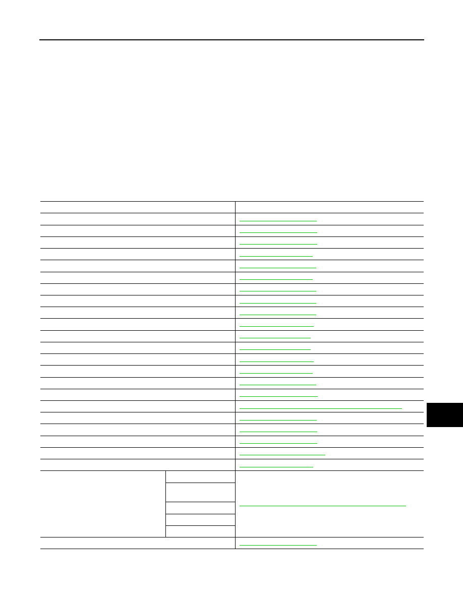
BCM CONTROL FUNCTION LIST

System

Reference

Combination switch reading system

BCS-11, "System Diagram"

Signal buffer system

BCS-15, "System Diagram"

Power consumption control system

BCS-17, "System Diagram"

Auto light system

EXL-9, "System Diagram"

Turn signal and hazard warning lamp system

EXL-14, "System Diagram"

Headlamp system

EXL-7, "System Diagram"

Parking, license plate, side maker and tail lamps system

EXL-16, "System Diagram"

Front fog lamp system

EXL-12, "System Diagram"

Exterior lamp battery saver system

EXL-18, "System Diagram"

Illumination control system

INL-11, "System Diagram"

Interior room lamp control system

INL-6, "System Diagram"

Interior room lamp battery saver system

INL-9, "System Diagram"

Illumination control system

INL-11, "System Diagram"

Front wiper and washer system

WW-6, "System Diagram"

Rear wiper and washer system

WW-10, "System Diagram"

Automatic air conditioner

HAC-15, "System Diagram"

Warning chime system

WCS-5, "WARNING CHIME SYSTEM : System Diagram"

Power door lock system

DLK-13, "System Diagram"

Nissan Vehicle Immobilizer System (NVIS) - NATS

SEC-16, "System Diagram"

Vehicle security system

SEC-21, "System Diagram"

Panic alarm

SEC-21, "System Description"

Rear window defogger system

DEF-4, "System Diagram"

Intelligent Key system/engine start system

Door lock function

DLK-16, "INTELLIGENT KEY SYSTEM : System Diagram"

Remote keyless entry 
function

Key reminder function

Warning function

Engine start function

Power window system

PWC-7, "System Diagram"

BCS-10

< SYSTEM DESCRIPTION >

[WITH INTELLIGENT KEY SYSTEM]

BODY CONTROL SYSTEM

Component Parts Location

INFOID:0000000009949696

Retained accessory power (RAP) system

PWC-7, "System Description"

Tire pressure monitoring system (TPMS) - AIR PRESSURE MONI-
TOR

WT-8, "TIRE PRESSURE MONITORING SYSTEM : System De-
scription"

System

Reference

1.

BCM

A.

Behind of instrument lower panel LH 
(Left side)

JPMIA1514ZZ

BCS

COMBINATION SWITCH READING SYSTEM

BCS-11

< SYSTEM DESCRIPTION >

[WITH INTELLIGENT KEY SYSTEM]

C

D

E

F

G

H

I

J

K

L

B

A

O

P

N

COMBINATION SWITCH READING SYSTEM

System Diagram

INFOID:0000000009949697

System Description

INFOID:0000000009949698

OUTLINE

• BCM reads the status of the combination switch (light, turn signal, wiper and washer) and recognizes the

status of each switch.

• BCM has a combination of 5 output terminals (OUTPUT 1 - 5) and 5 input terminals (INPUT 1 - 5). It reads a

maximum of 20 switch status.

COMBINATION SWITCH MATRIX

Combination switch circuit

Combination switch INPUT-OUTPUT system list

JPMIA1543GB

System

INPUT 1

INPUT 2

INPUT 3

INPUT 4

INPUT 5

OUTPUT 1

FR WASHER

FR WIPER LOW

TURN LH

TURN RH

OUTPUT 2

FR WIPER HI

FR WIPER INT

PASSING

HEADLAMP 1

OUTPUT 3

INT VOLUME 1

RR WASHER

HEADLAMP 2

HI BEAM

JPMIA1544GB

BCS-12

< SYSTEM DESCRIPTION >

[WITH INTELLIGENT KEY SYSTEM]

COMBINATION SWITCH READING SYSTEM

NOTE:

Headlamp has a dual system switch.

COMBINATION SWITCH READING FUNCTION

Description

• BCM reads the status of the combination switch at 10 ms interval normally.

NOTE:
BCM reads the status of the combination switch at 60 ms interval when BCM is controlled at low power con-
sumption control mode.

• BCM operates as follows and judges the status of the combination switch.
- It operates the transistor on OUTPUT side in the following order: OUTPUT 1 

 2 

 3 

 4 

 5, and outputs

voltage waveform.

- The voltage waveform of OUTPUT corresponding to the formed circuit is input into the interface on INPUT

side if any (1 or more) switches are ON.

- It reads this change of the voltage as the status signal of the combination switch.

Operation Example

In the following operation example, the combination of the status signals of the combination switch is replaced
as follows: INPUT 1 - 5 to “1 - 5” and OUTPUT 1 - 5 to “A - E”.

Example 1: When a switch (TAIL LAMP switch) is turned ON

OUTPUT 4

RR WIPER INT

INT VOLUME 3

AUTO LIGHT

TAIL LAMP

OUTPUT 5

INT VOLUME 2

RR WIPER

FR FOG

System

INPUT 1

INPUT 2

INPUT 3

INPUT 4

INPUT 5

JPMIA0609GB

JMMIA0326GB


Content   ..  38  39  40  41   ..