Nissan Cube. Manual - part 30
AV
CONTROL SIGNAL CIRCUIT
AV-113
< DTC/CIRCUIT DIAGNOSIS >
[AUDIO WITH NAVIGATION]
C
D
E
F
G
H
I
J
K
L
M
B
A
O
P
CONTROL SIGNAL CIRCUIT
Description
INFOID:0000000009949620
TEL adapter unit identifies the vehicle model according to the control signal and performs the control.
Diagnosis Procedure
INFOID:0000000009949621
1.
CHECK CONTINUITY CONTROL SIGNAL CIRCUIT
1.
Turn ignition switch OFF.
2.
Disconnect TEL adapter unit connector.
3.
Check continuity between TEL adapter unit harness connector and ground.
Is the inspection result normal?
YES
>> Replace TEL adapter unit. Refer to
NO
>> Repair harness or connector.
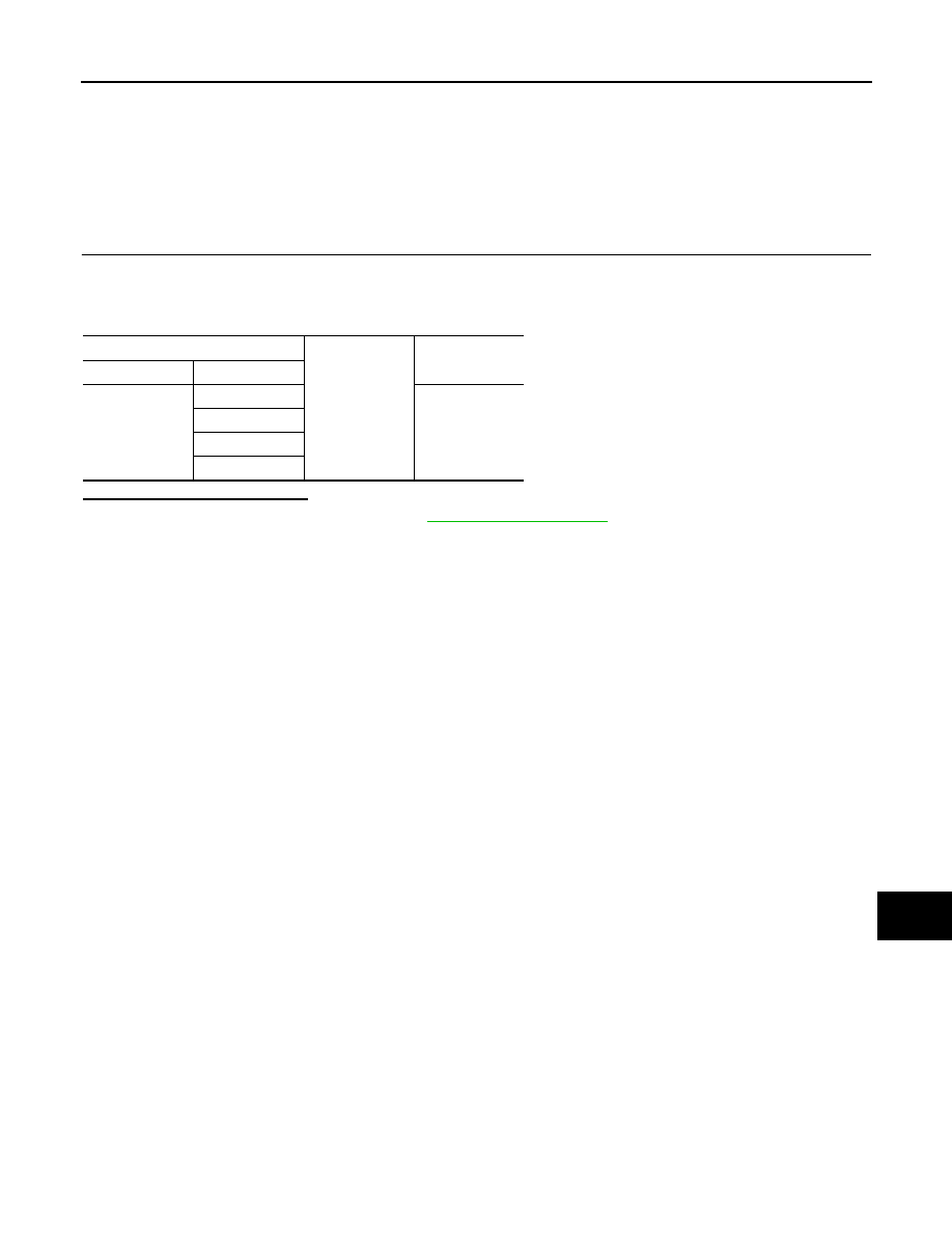
TEL adapter unit
Ground
Continuity
Connector
Terminals
B54
20
Existed
21
24
27