Nissan Versa Note. Manual - part 852
WCS-22
< ECU DIAGNOSIS INFORMATION >
COMBINATION METER
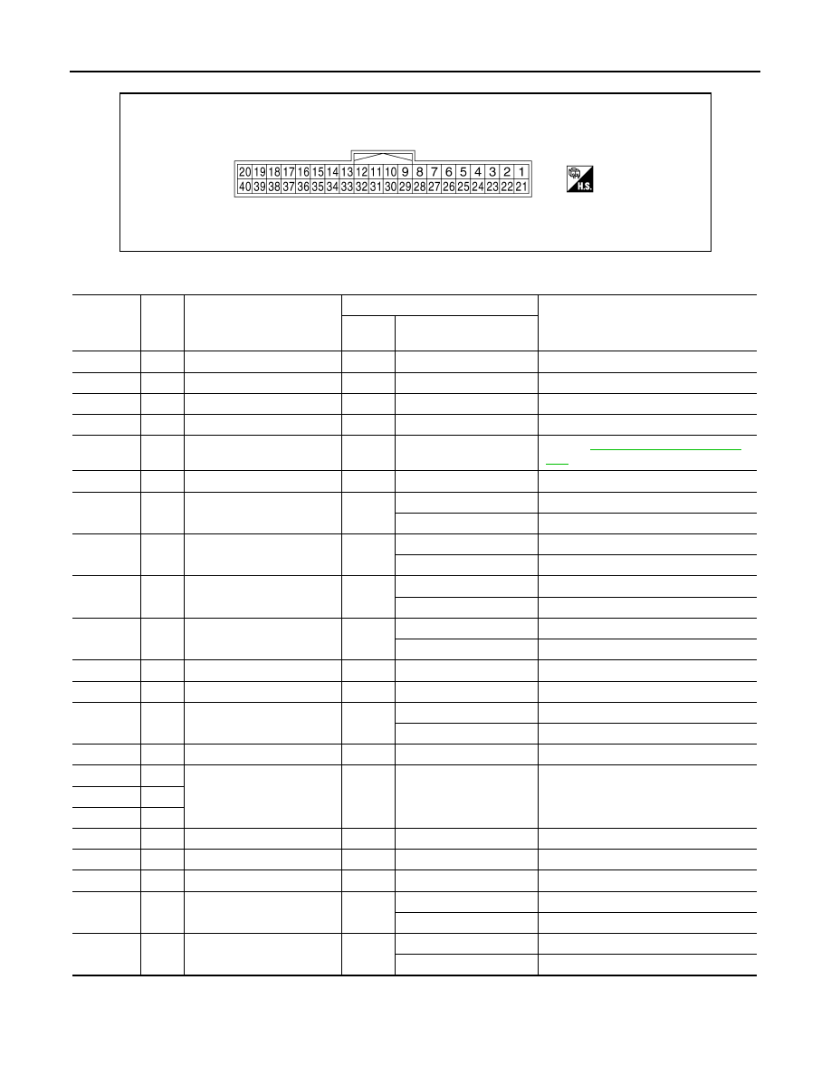
TERMINAL LAYOUT
PHYSICAL VALUES
Fail-safe
INFOID:0000000009693752
The combination meter activates the fail-safe control if CAN communication with each unit is malfunctioning.
JSNIA5390ZZ
Terminal
No.
Wire
color
Item
Condition
Reference value (V)
(Approx.)
Ignition
switch
Operation or condition
1
L
CAN-H
—
—
—
2
P
CAN-L
—
—
—
3
SB
2P/R
—
—
—
4
LG
8P/R
—
—
—
6
W
Fuel level sensor signal (+)
—
—
Refer to
7
V
Air bag
—
—
—
8
P
O/D OFF switch
ON
O/D OFF switch pressed
0
O/D OFF switch released
Battery voltage
9
V
Seat belt buckle switch LH
ON
Unfastened (ON)
0
Fastened (OFF)
Battery voltage
10
SB
Parking Brake switch
ON
Parking brake is inactive
0
Parking brake is active
Battery voltage
11
BR
Brake fluid level switch
ON
Brake fluid level low
0
Brake fluid level normal
Battery voltage
13
B
Illumination control
—
—
—
15
R
Ignition switch ON or ACC
—
—
Battery voltage
17
V
Washer fluid level switch
(Canada models)
ON
Washer fluid level low
0
Washer fluid level normal
Battery voltage
18
R/Y
Security
—
—
—
21
B
Ground
—
—
0
22
B
23
B
24
GR
Fuel level sensor ground (-)
ON
—
0
27
R/W
Battery power supply
OFF
—
Battery voltage
28
GR
Ignition switch ON or START
ON
—
Battery voltage
29
G
Seat belt buckle switch RH
ON
Unfastened (ON)
0
Fastened (OFF)
Battery voltage
38
Y
Generator
ON
Generator voltage low
0
Generator voltage normal
Battery voltage