Nissan Versa Note. Manual - part 621
PCS-94
< DTC/CIRCUIT DIAGNOSIS >
[POWER DISTRIBUTION SYSTEM]
B26F2 IGNITION RELAY
B26F2 IGNITION RELAY
DTC Logic
INFOID:0000000009579026
DTC DETECTION LOGIC
DTC CONFIRMATION PROCEDURE
1.
PERFORM SELF DIAGNOSTIC RESULT
1. Turn ignition switch to ON, and wait for 2 seconds or more.
2. Check Self Diagnosis Result of BCM with CONSULT.
Is DTC B26F2 detected?
YES
>> Go to
NO
>> Inspection End.
Diagnosis Procedure
INFOID:0000000009579027
Regarding Wiring Diagram information, refer to
.
1.
CHECK IPDM E/R SELF-DIAGNOSTIC RESULT
1. Erase IPDM E/R DTCs.
2. Turn ignition switch OFF.
3. Turn ignition switch ON.
4. Perform Self Diagnostic Result of IPDM E/R with CONSULT.
Are any DTCs detected?
YES
>> Refer to
NO
>> GO TO 2.
2.
CHECK IGNITION RELAY-1 CONTROL SIGNAL (IPDM E/R)
1. Turn ignition switch OFF.
2. Check voltage between IPDM E/R connector E47 and ground.
Is the inspection result normal?
YES
>> Replace IPDM E/R. Refer to
PCS-31, "Removal and Installation"
NO
>> GO TO 3.
3.
CHECK IGNITION RELAY-1 CONTROL SIGNAL CIRCUIT (IPDM E/R)
1. Turn ignition switch OFF.
2. Disconnect BCM connector M98 and IPDM E/R connector E47.
3. Check continuity between IPDM E/R connector E47 and ground.
Is the inspection result normal?
YES
>> GO TO 4.
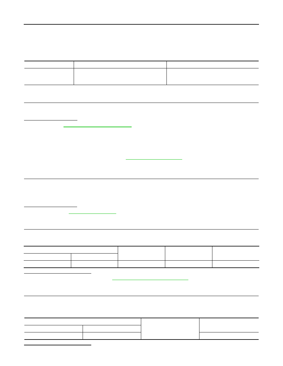
CONSULT Display
DTC detecting condition
Possible cause
IGN RELAY ON
[B26F2]
BCM transmits the ignition relay control signal, but
does not receive ignition switch ON signal (CAN)
from IPDM E/R.
• Harness or connectors
• BCM
• IPDM E/R
IPDM E/R
Ground
Condition
Voltage
(Approx.)
Connector
Terminal
E47
90
—
Ignition: OFF
Battery voltage
IPDM E/R
Ground
Continuity
Connector
Terminal
E47
90
No