Nissan Versa Note. Manual - part 558
LAN-80
< DTC/CIRCUIT DIAGNOSIS >
[CAN SYSTEM (TYPE 502)]
CAN COMMUNICATION CIRCUIT
CAN COMMUNICATION CIRCUIT
Diagnosis Procedure
INFOID:0000000009760138
1.
CONNECTOR INSPECTION
1. Turn the ignition switch OFF.
2. Disconnect the battery cable from the negative terminal.
3. Disconnect all the unit connectors on CAN communication system.
4. Check terminals and connectors for damage, bend and loose connection.
Is the inspection result normal?
YES
>> GO TO 2.
NO
>> Repair the terminal and connector.
2.
CHECK HARNESS CONTINUITY (SHORT CIRCUIT)
Check the continuity between the data link connector terminals.
Is the inspection result normal?
YES
>> GO TO 3.
NO
>> Check the harness and repair the root cause.
3.
CHECK HARNESS CONTINUITY (SHORT CIRCUIT)
Check the continuity between the data link connector and the ground.
Is the inspection result normal?
YES
>> GO TO 4.
NO
>> Check the harness and repair the root cause.
4.
CHECK ECM AND BCM TERMINATION CIRCUIT
1. Remove the ECM and the BCM.
2. Check the resistance between the ECM terminals.
3. Check the resistance between the BCM terminals.
Is the measurement value within the specification?
YES
>> GO TO 5.
NO
>> Replace the ECM and/or the BCM.
5.
CHECK SYMPTOM
Connect all the connectors. Check if the symptoms described in the “Symptom (Results from interview with
customer)” are reproduced.
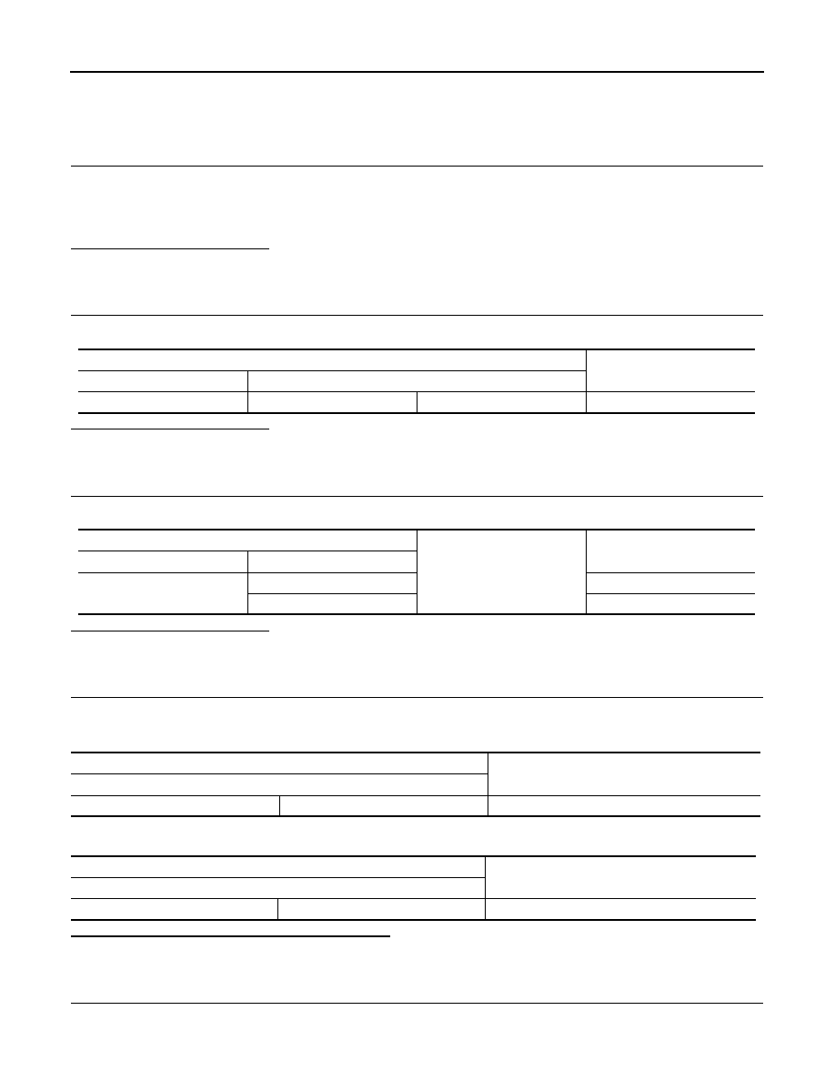
Data link connector
Continuity
Connector No.
Terminal No.
M22
6
14
Not existed
Data link connector
Ground
Continuity
Connector No.
Terminal No.
M22
6
Not existed
14
Not existed
ECM
Resistance (
Ω)
Terminal No.
84
83
Approx. 108 – 132
BCM
Resistance (
Ω)
Terminal No.
39
40
Approx. 108 – 132