Nissan Versa Note. Manual - part 503


  Index      Nissan     Nissan Versa Note (2014 year) - Service and Repair Manual


Search            


Content   ..  501  502  503  504   ..


Nissan Versa Note. Manual - part 503


FRONT BLOWER MOTOR

HAC-47

< DTC/CIRCUIT DIAGNOSIS >

[MANUAL AIR CONDITIONING]

C

D

E

F

G

H

J

K

L

M

A

B

HAC

N

O

P

NO

>> Replace front blower motor resistor. Refer to 

HAC-59, "Removal and Installation"

.

10.

CHECK FAN SWITCH

Check fan switch. Refer to 

HAC-47, "Component Inspection (Fan Switch)"

.

Is the inspection result normal?

YES

>> Replace front blower motor. Refer to 

VTL-9, "Removal and Installation"

.

NO

>> Replace front air control. Refer to 

HAC-56, "Removal and Installation"

.

Component Inspection (Front Blower Motor)

INFOID:0000000009541005

1.

CHECK FRONT BLOWER MOTOR

1. Connect battery voltage to terminal 1 of front blower motor.

2. Connect ground to terminal 2 of front blower motor.
Does the front blower motor operate?

YES

>> Intermittent incident. Refer to 

GI-41, "Intermittent Incident"

.

NO

>> Replace front blower motor. Refer to 

VTL-9, "Removal and Installation"

.

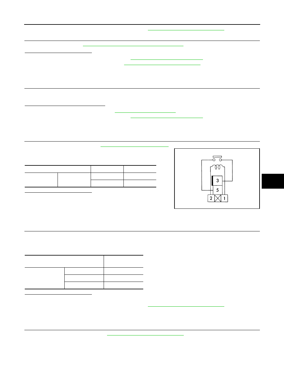
Component Inspection (Blower Relay)

INFOID:0000000009541006

1.

CHECK BLOWER RELAY

1. Remove blower relay. Refer to 

PG-58, "Terminal Arrangement"

2. Check continuity between blower relay terminal 3 and 5 when

the voltage is supplied between terminal 1 and 2. 

Is the inspection result normal?

YES

>> Inspection End.

NO

>> Replace blower relay.

Component Inspection (Front Blower Motor Resistor)

INFOID:0000000009541007

1.

CHECK FRONT BLOWER MOTOR RESISTOR

1. Disconnect front blower motor resistor connector.

2. Check resistance between front blower motor resistor terminals. Refer to applicable table for the normal

value.

Is the inspection result normal?

YES

>> Inspection End.

NO

>> Replace front blower motor resistor. Refer to 

HAC-59, "Removal and Installation"

.

Component Inspection (Fan Switch)

INFOID:0000000009541008

1.

CHECK FAN SWITCH

1. Remove front air control. Refer to 

HAC-56, "Removal and Installation"

2. Check continuity between front air control terminals. 

Terminal

Voltage

Continuity

3

5

ON

Yes

OFF

No

JSIIA1551ZZ

Terminal

Resistance: 

(Approx.)

3

1

0.54

4

1.56

2

3.07

HAC-48

< DTC/CIRCUIT DIAGNOSIS >

[MANUAL AIR CONDITIONING]

FRONT BLOWER MOTOR

Is the inspection result normal?

YES

>> Inspection End.

NO

>> Replace front air control. Refer to 

HAC-56, "Removal and Installation"

.

Terminal

Condition

Continuity

Fan control dial (fan 

switch) position

6

4

1st

Yes

3

2nd

2

3rd

1

4th

MAGNET CLUTCH

HAC-49

< DTC/CIRCUIT DIAGNOSIS >

[MANUAL AIR CONDITIONING]

C

D

E

F

G

H

J

K

L

M

A

B

HAC

N

O

P

MAGNET CLUTCH

Description

INFOID:0000000009541009

SYSTEM DESCRIPTION

When the blower speed dial is in one of the fan speed positions, the front air control outputs a fan ON signal to

the BCM. When the A/C switch is pressed, the A/C switch LED illuminates and the front air control outputs a

compressor ON signal to the BCM. Any mode control button can be selected. As long as the BCM receives a

compressor ON signal and a fan ON signal from the front air control, the conditions required for the BCM to

transmit a compressor ON request to the ECM have been met. 

The BCM sends a compressor ON signal to ECM, via CAN communication line.

The ECM judges whether the compressor can be turned ON, based on each sensor status (refrigerant pres-

sure sensor signal, throttle angle sensor, etc.). If it judges the compressor can be turned ON, it sends a com-

pressor ON signal to IPDM E/R, via CAN communication line.

Upon receipt of a compressor ON signal from ECM, IPDM E/R turns the A/C relay ON to operate the compres-

sor.

Component Function Check

INFOID:0000000009541010

1.

CHECK MAGNET CLUTCH OPERATION

Perform auto active test of IPDM E/R. Refer to 

PCS-11, "CONSULT Function (IPDM E/R)"

 (with Intelligent

Key) or 

PCS-40, "CONSULT Function (IPDM E/R)"

 (without Intelligent Key). 

Is the inspection result normal?

YES

>> Inspection End.

NO

>> Refer to 

HAC-49, "Diagnosis Procedure"

.

Diagnosis Procedure

INFOID:0000000009541011

Regarding Wiring Diagram information, refer to 

HAC-24, "Wiring Diagram"

.

1.

CHECK FUSE

Check 10A fuse (No. 42, located in IPDM E/R). 

NOTE:

Refer to 

PG-60, "IPDM E/R Terminal Arrangement"

Is the inspection result normal?

YES

>> GO TO 2.

NO

>> Replace the blown fuse after repairing the affected circuit. 

2.

CHECK MAGNET CLUTCH

1. Turn ignition switch OFF.

2. Disconnect compressor connector.

3. Directly apply battery voltage to the magnet clutch. Check for operation visually and by sound. 
Does it operate normally?

YES

>> GO TO 3.

NO

>> Replace magnet clutch. Refer to 

HA-25, "Removal and Installation"

.

3.

CHECK MAGNET CLUTCH POWER SUPPLY CIRCUIT FOR OPEN

1. Disconnect IPDM E/R connector.

2. Check continuity between IPDM E/R harness connector and compressor harness connector. 

HAC-50

< DTC/CIRCUIT DIAGNOSIS >

[MANUAL AIR CONDITIONING]

MAGNET CLUTCH

Is the inspection result normal?

YES

>> Replace IPDM E/R. Refer to 

PCS-31, "Removal and Installation"

 (with Intelligent Key) or 

PCS-60,

"Removal and Installation"

 (without Intelligent Key).

NO

>> Repair harness or connector. 

IPDM E/R

Compressor

Continuity

Connector

Terminal

Connector

Terminal

E45

28

F3

1

Yes


Content   ..  501  502  503  504   ..