Nissan Versa Note. Manual - part 500


  Index      Nissan     Nissan Versa Note (2014 year) - Service and Repair Manual


Search            


Content   ..  498  499  500  501   ..


Nissan Versa Note. Manual - part 500


A/C ON SIGNAL

HAC-35

< DTC/CIRCUIT DIAGNOSIS >

[MANUAL AIR CONDITIONING]

C

D

E

F

G

H

J

K

L

M

A

B

HAC

N

O

P

DTC/CIRCUIT DIAGNOSIS

A/C ON SIGNAL

Component Function Check

INFOID:0000000009540997

1.

CHECK A/C ON SIGNAL

With CONSULT

1. Turn ignition switch ON.

2. Operate front blower motor.

3. Select “AIR CONDITIONER” of “BCM” using CONSULT.

4. Select “AIR COND SW” in “DATA MONITOR” mode, and check status under the following condition.

Is the inspection result normal?

YES

>> Inspection End.

NO

>> Refer to 

HAC-35, "Diagnosis Procedure"

.

Diagnosis Procedure

INFOID:0000000009702393

1.

CHECK A/C SWITCH POWER SUPPLY

1. Turn ignition switch OFF.

2. Disconnect front air control connector.

3. Turn ignition switch ON.

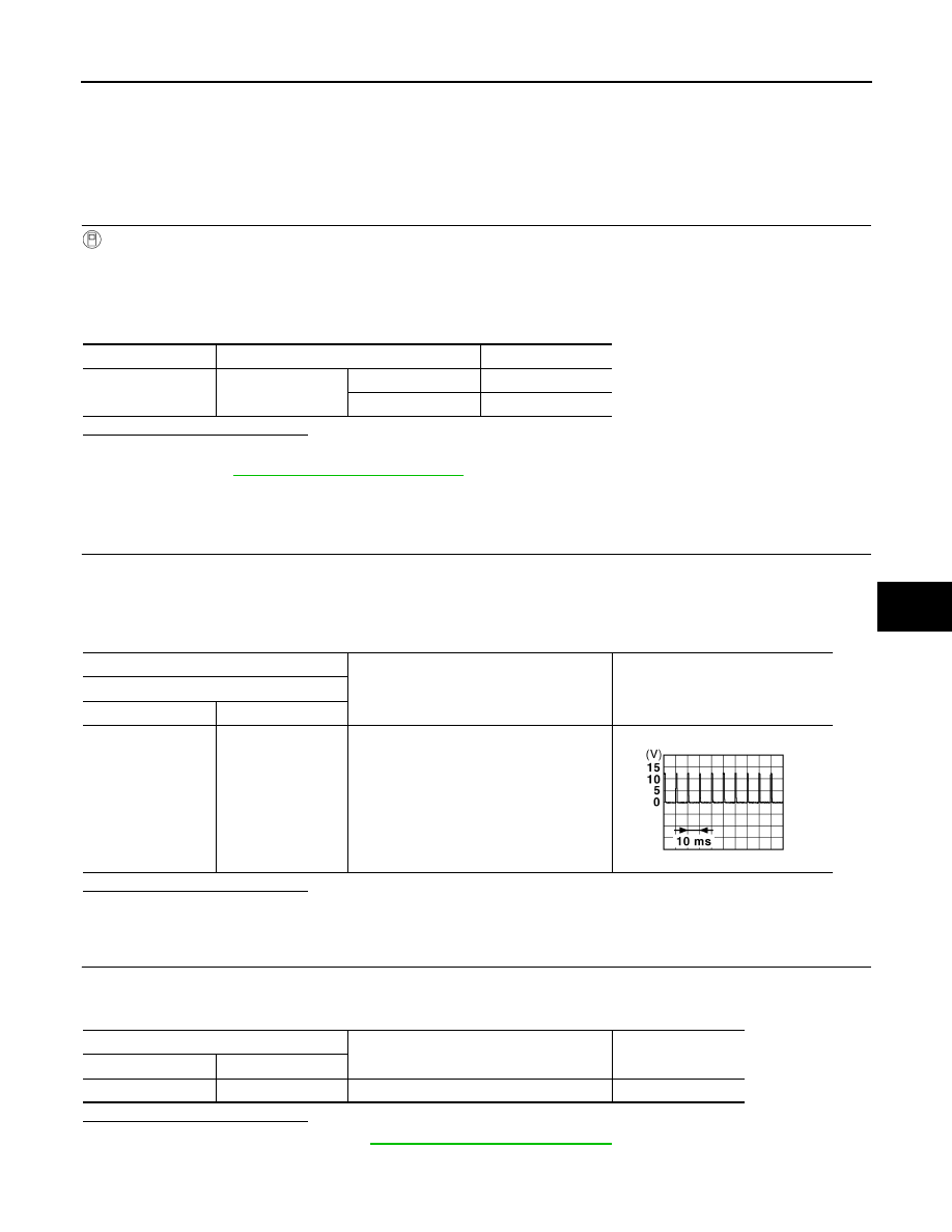
4. Check output waveform between front air control harness connector and ground with using oscilloscope.

Is the inspection result normal?

YES

>> GO TO 2.

NO

>> GO TO 3.

2.

CHECK A/C SWITCH GROUND CIRCUIT FOR OPEN

1. Turn ignition switch OFF.

2. Check continuity between front air control harness connector and ground.

Is the inspection result normal?

YES

>> Check A/C switch. Refer to 

HAC-36, "Component Inspection"

.

NO

>> Repair harness or connector.

Monitor item

Condition

Status

AIR COND SW

A/C switch

ON

On

OFF

Off

+

Output waveform

Front air control

Connector

Terminal

M33

13

Ground

JPMIA0012GB

Front air control

Continuity

Connector

Terminal

M33

6

Ground

Yes

HAC-36

< DTC/CIRCUIT DIAGNOSIS >

[MANUAL AIR CONDITIONING]

A/C ON SIGNAL

3.

CHECK A/C SWITCH POWER SUPPLY CIRCUIT FOR OPEN

1. Turn ignition switch OFF.

2. Disconnect BCM connector.

3. Check continuity between front air control harness connector and BCM harness connector.

Is the inspection result normal?

YES

>> GO TO 4.

NO

>> Repair harness or connector.

4.

CHECK A/C SWITCH POWER SUPPLY CIRCUIT FOR SHORT

Check continuity between front air control harness connector and ground.

Is the inspection result normal?

YES

>> Replace BCM. Refer to 

BCS-70, "Removal and Installation"

 (with Intelligent Key) or 

BCS-127,

"Removal and Installation"

 (without Intelligent Key).

NO

>> Repair harness or connector.

Component Inspection

INFOID:0000000009540999

1.

CHECK A/C CONTROL

Check continuity front air control terminals.

Is the inspection result normal?

YES

>> Inspection End.

NO

>> Replace front air control. Refer to 

HAC-56, "Removal and Installation"

.

Front air control

BCM

Continuity

Connector

Terminal

Connector

Terminal

M33

13

M18 (without Intelligent Key)

27

Yes

M97 (with Intelligent Key)

Front air control

Continuity

Connector

Terminal

M33

13

Ground

No

Terminal

Condition

Continuity

13

6

A/C switch: ON

Yes

BLOWER FAN ON SIGNAL

HAC-37

< DTC/CIRCUIT DIAGNOSIS >

[MANUAL AIR CONDITIONING]

C

D

E

F

G

H

J

K

L

M

A

B

HAC

N

O

P

BLOWER FAN ON SIGNAL

Component Function Check

INFOID:0000000009541000

1.

CHECK BLOWER FAN ON SIGNAL

With CONSULT

1. Turn ignition switch ON.

2. Select “AIR CONDITIONER” of “BCM” using CONSULT.

3. Select “FAN ON SIG” in “DATA MONITOR” mode, and check status under the following condition.

Is the inspection result normal?

YES

>> Inspection End.

NO

>> Refer to 

HAC-37, "Diagnosis Procedure"

.

Diagnosis Procedure

INFOID:0000000009541001

Regarding Wiring Diagram information, refer to 

HAC-24, "Wiring Diagram"

 or 

HAC-29, "Wiring Diagram"

.

1.

CHECK BLOWER FAN ON SIGNAL

1. Turn ignition switch OFF.

2. Disconnect front air control harness connector.

3. Turn ignition switch ON.

4. Check output waveform between front air control and ground with using oscilloscope.

Is the inspection result normal?

YES

>> Replace front air control. Refer to 

HAC-56, "Removal and Installation"

.

NO

>> GO TO 2.

2.

CHECK BLOWER FAN ON SIGNAL CIRCUIT FOR OPEN

1. Turn ignition switch OFF.

2. Disconnect BCM connector.

3. Check continuity front air control harness connector and BCM harness connector.

Monitor item

Condition

Status

FAN ON SIG

Fan control dial

Except OFF position

On

OFF position

Off

+

Output waveform

Front air control

Connector

Terminal

M33

5

Ground

PKIB4960J

Front air control

BCM

Continuity

Connector

Terminal

Connector

Terminal

M33

5

M18 (without Intelligent Key system)

28

Yes

M97 (with Intelligent Key system)

HAC-38

< DTC/CIRCUIT DIAGNOSIS >

[MANUAL AIR CONDITIONING]

BLOWER FAN ON SIGNAL

Is the inspection result normal?

YES

>> GO TO 3.

NO

>> Repair harness or connector.

3.

CHECK BLOWER FAN ON SIGNAL CIRCUIT FOR SHORT

Check continuity between front air control harness connector and ground.

Is the inspection result normal?

YES

>> Replace BCM. Refer to 

BCS-70, "Removal and Installation"

 (with Intelligent Key) or 

BCS-127,

"Removal and Installation"

 (without Intelligent Key).

NO

>> Repair harness or connector.

Front air control

Continuity

Connector

Terminal

M33

5

Ground

No


Content   ..  498  499  500  501   ..