Nissan Versa Note. Manual - part 488


  Index      Nissan     Nissan Versa Note (2014 year) - Service and Repair Manual


Search            


Content   ..  486  487  488  489   ..


Nissan Versa Note. Manual - part 488


HA-22

< PERIODIC MAINTENANCE >

OIL

Oil Adjusting Procedure for Compressor Replacement

INFOID:0000000008968517

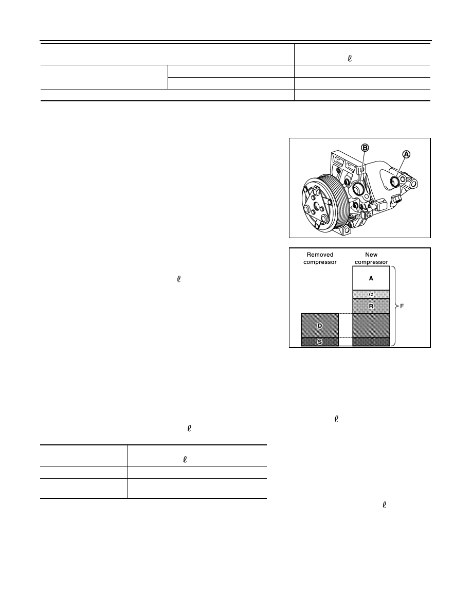
1. Drain oil from removed compressor and measure amount drained.

• Drain oil from high-pressure port (A) and low-pressure port (B)

while rotating magnet clutch.

• Measure total amount of oil that is drained from removed com-

pressor.

2. Drain oil from a new compressor that is calculated according to

the following conditions.

CAUTION:

If oil amount that is drained from removed compressor is less than 60 m  (2.1 Imp fl oz.), perform
calculation by setting “D” as 40 m  (1.4 Imp fl oz.).

Example: Oil amount to be drained from a new compressor when replacing compressor [m  (Imp fl oz.)]

[D = 60 (2.1), 

α = 5 (0.2)]

120 (4.2) 

− [60 (2.1) + 20 (0.7) + 5 (0.2)] = 35 (1.1)

3. Install compressor and check the operation.

Refrigerant leak is detected

Large amount leakage

30 (1.1)

Small amount leakage

Oil amount that is recycled together with refrigerant during recycle operation

α

Conditions

Oil amount to be added to A/C system

m  (Imp fl oz.)

JMIIA0940ZZ

Amount to be drained (A) [m  (Imp fl oz.)] = F 

 (D 

+ S + R + 

α)

F:

Oil amount that a new compressor contains 
[120 (4.2)]

D: Oil amount that is drained from removed com-

pressor

S: Oil amount that remains inside of removed 

compressor [20 (0.7)]

R: Oil amount to be added according to compo-

nents that are removed except compressor

α: Oil amount that is recycled together with re-

frigerant during recycle operation

Conditions

Oil amount to be added to A/C system

m  (Imp fl oz.)

Replace evaporator

35 (1.2)

Replace condenser (in-
cludes liquid tank)

20 (0.7)

JPIIA1455GB

PERFORMANCE TEST

HA-23

< PERIODIC MAINTENANCE >

C

D

E

F

G

H

J

K

L

M

A

B

HA

N

O

P

PERFORMANCE TEST

Inspection

INFOID:0000000008968518

INSPECTION PROCEDURE

1. Connect recovery/recycling/recharging equipment (for HFC-134a) or manifold gauge set.
2. Start the engine, and set to the following condition.

Test condition

3. Maintain test condition until A/C system becomes stable. (Approximately 10 minutes)
4. Check that test results of “recirculating-to-discharge air temperature” and “ambient air temperature-to-

operating pressure” are within the specified value.

5. When test results are within the specified value, inspection is complete.

If any test result is out of the specified value, perform diagnosis by manifold gauge set. Refer to 

HA-14,

"Symptom Table"

.

RECIRCULATING-TO-DISCHARGE AIR TEMPERATURE TABLE

FRONT

AMBIENT AIR TEMPERATURE-TO-OPERATING PRESSURE TABLE

Surrounding condition

In a well-ventilated place away from direct sunlight.

Vehicle condition

Doors

Closed

Door glass

Closed

Hood

Open

Engine speed

Idle speed

A/C condition (front/rear)

Temperature control

Full cold

A/C switch

ON

Air outlet

VENT (ventilation)

Intake door position

Recirculation

Blower speed

Maximum

Inside air (Recirculating air) at blower assembly inlet

Discharge air temperature from center ventilator

°C (°F)

Relative humidity

%

Air temperature

°C (°F)

50 – 60

20 (68)

4.7 - 6.7 (40 - 44)

25 (77)

8.6 - 11.1 (47 - 52)

30 (86)

12.6 - 15.6 (55 - 60)

35 (95)

19.0 - 22.5 (66 - 73)

60 – 70

20 (68)

6.7 - 8.7 (44 - 48)

25 (77)

11.1 - 13.6 (52 - 56)

30 (86)

15.6 - 18.6 (60 - 65)

35 (95)

22.5 - 26.0 (73 - 79)

HA-24

< PERIODIC MAINTENANCE >

PERFORMANCE TEST

Fresh air

High-pressure (Discharge side)

kPa (kg/cm

2

, psi)

Low-pressure (Suction side)

kPa (kg/cm

2

, psi)

Relative humidity

%

Air temperature

°C (°F)

50 – 70

25 (77)

900 - 1,112

(9.2 - 11.3, 130.5 - 161.2)

159 - 194

(1.6 - 2.0, 23.1 - 28.1)

30 (86)

1,073 - 1,312

(10.9 - 13.4, 155.6 - 190.2)

211 - 259

(2.2 - 3.1, 30.6 - 37.6)

35 (95)

1,445 - 1,766

(14.7 - 18.0, 209.5 - 256.1)

247 - 300

(2.5 - 3.1, 35.8 - 43.5)

40 (104)

1,650 - 2,017

(16.8 - 20.6, 239.3 - 292.5)

290 - 355

(3.0 - 3.6, 42.1 - 51.5)

COMPRESSOR

HA-25

< REMOVAL AND INSTALLATION >

C

D

E

F

G

H

J

K

L

M

A

B

HA

N

O

P

REMOVAL AND INSTALLATION

COMPRESSOR

Exploded View

INFOID:0000000008968522

Removal and Installation

INFOID:0000000009395290

REMOVAL

1. Discharge the refrigerant. Refer to 

HA-19, "Recycle Refrigerant"

.

2. Remove front grille. Refer to 

EXT-29, "Removal and Installation"

.

3. Remove fender protector (RH). Refer to 

EXT-36, "Removal and Installation"

.

4. Remove low-pressure flexible hose and high-pressure flexible hose from compressor.

CAUTION:

Cap or wrap the joint of the A/C hoses and compressor with suitable material such as vinyl tape to

avoid the entry of air.

5. Remove drive belt. Refer to 

EM-16, "Removal and Installation"

.

6. Disconnect magnet clutch harness connector.
7. Remove bolts and compressor.

INSTALLATION

Installation is in the reverse order of removal.

CAUTION:

• Do not reuse O-rings.

• Apply compressor oil to the new O-rings of the low-pressure flexible hose and high-pressure flexible

hose for installation.

• Perform oil adjusting procedure before installing new compressor. Refer to 

HA-22, "Oil Adjusting

Procedure for Compressor Replacement"

.

• Check drive belt tension after installing compressor. Refer to 

EM-17, "Adjustment"

.

Inspection

INFOID:0000000009395291

CHECK DISC TO PULLEY CLEARANCE

JMIIA1211GB

1.

High-pressure flexible hose

2.

O-ring

3.

Compressor

4.

Low-pressure flexible hose

A. To condenser

B. To evaporator


Content   ..  486  487  488  489   ..