Nissan Versa Note. Manual - part 475


  Index      Nissan     Nissan Versa Note (2014 year) - Service and Repair Manual


Search            


Content   ..  473  474  475  476   ..


Nissan Versa Note. Manual - part 475


CONSULT/GST CHECKING SYSTEM

GI-49

< BASIC INSPECTION >

C

D

E

F

G

H

I

J

K

L

M

B

GI

N

O

P

CONSULT/GST CHECKING SYSTEM

Description

INFOID:0000000009472988

NOTE:

This vehicle is diagnosed using the CONSULT-III plus.

• When CONSULT is connected with a data link connector equipped

on the vehicle side, it will communicate with the control unit

equipped in the vehicle and then enable various kinds of diagnos-

tic tests.

• Refer to “CONSULT-III plus Operation Manual” for more informa-

tion.

Function and System Application

INFOID:0000000009472989

x: Applicable
1: With continuously variable transmission
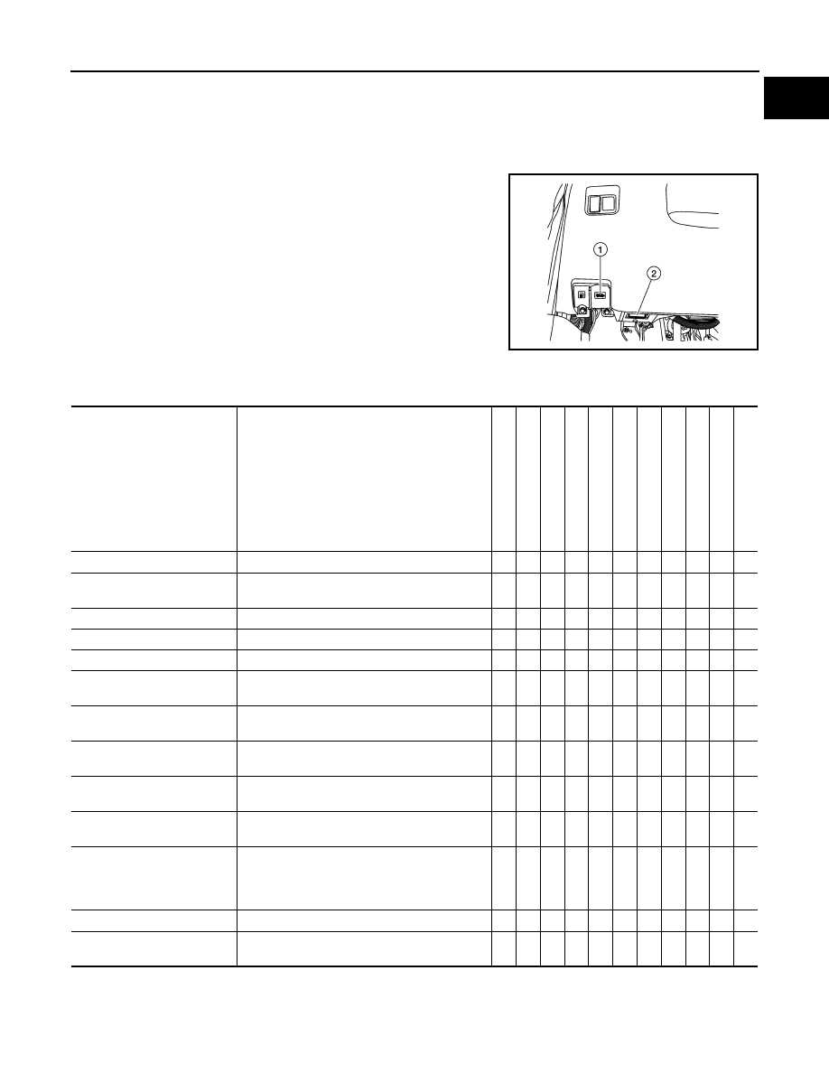
1

: Hood release handle

2

: Data link connector

ALAIA0095ZZ

Diagnosis (All Systems)

Description

ENGINE

ABS

MET

E

R/M

&

A

BC

M

AIR B

A

G

TRANSMISSION

1

EPS

IPDM E/R

AV

M

MUL

T

I A

V

OCCUP

ANT DETECTION

Self Diagnostic Result

The ECU self diagnostic results are displayed.

x

x

x

x

x

x

x

x

x

x

-

Data Monitor

The ECU input/output data is displayed in real 
time.

x

x

x

x

x

x

x

x

x

x

-

Work support

The settings for ECU functions can be changed.

x

x

x

x

-

x

-

-

x

-

x

Active Test

The ECU activates outputs to test components.

x

x

-

x

-

-

-

x

-

-

-

ECU identification

The ECU part number is displayed.

x

x

-

x

x

x

x

x

x

x

-

DTC Work Support

The status of system monitoring tests and the 
self diagnosis status/results can be confirmed.

x

-

-

-

-

-

-

-

-

-

-

Warning History

Displays the history of the combination meter 
warning lamp indicators.

-

-

x

-

-

-

-

-

-

-

-

TROUBLE DIAG RECORD

Self diagnostic history and trouble diagnosis 
records in ECU are displayed.

-

-

-

-

x

-

-

-

-

-

-

CAN Diag

This mode displays network diagnostic results of 
CAN communication using a diagram.

x

x

x

x

x

x

x

x

x

x

-

CAN DIAG SUPPORT MNTR

The result of transmit/receive diagnosis of CAN 
communication is displayed.

x

x

x

x

x

x

x

x

x

x

-

Configuration 

• The vehicle specification can be read and 

saved.

• The vehicle specification can be written when 

replacing ECU.

-

-

-

x

-

-

-

-

-

-

-

CALIB DATA

The calibration values of the ECU are displayed.

-

-

-

-

-

x

-

-

-

-

-

SRT & P-DTC Confirmation

The status of system monitoring tests and the 
self diagnosis status/results can be confirmed.

x

-

-

-

-

-

-

-

-

-

-

GI-50

< BASIC INSPECTION >

CONSULT/GST CHECKING SYSTEM

CONSULT Data Link Connector (DLC) Circuit

INFOID:0000000009472990

INSPECTION PROCEDURE

If the CONSULT cannot diagnose the system properly, check the following items.

NOTE:

The DDL2 circuits and CAN communication lines from DLC pins 6, 7 and 14 may be connected to more than

one system. A short in a DDL circuit or CAN lines connected to a control unit in one system may affect CON-

SULT access to other systems. For a complete DDL circuit layout, refer to 

GI-51, "Wiring Diagram - CON-

SULT/GST CHECKING SYSTEM"

. For a complete CAN line layout, refer to 

LAN-32, "Wiring Diagram"

.

Symptom

Check item

CONSULT cannot access any 
system.

• CONSULT DLC power supply circuit (Terminal 8) and ground circuit (Terminal 4) 

CONSULT cannot access indi-
vidual system. (Other systems 
can be accessed.)

• Power supply and ground circuit for the control unit of the system (For detailed circuit, refer to wiring 

diagram for each system.)

• Open or short circuit between the system and CONSULT DLC (For detailed circuit, refer to wiring 

diagram for each system.)

• Open or short circuit CAN communication line. Refer to 

LAN-15, "Trouble Diagnosis Flow Chart"

.

CONSULT/GST CHECKING SYSTEM

GI-51

< BASIC INSPECTION >

C

D

E

F

G

H

I

J

K

L

M

B

GI

N

O

P

Wiring Diagram - CONSULT/GST CHECKING SYSTEM

INFOID:0000000009472991

AAAWA0060GB

GW-1

BODY EXTERIOR, DOORS, ROOF & VEHICLE SECURITY

C

D

E

F

G

H

I

J

L

M

SECTION 

GW

A

B

GW

N

O

P

CONTENTS

GLASS & WINDOW SYSTEM

PRECAUTION ...............................................

2

PRECAUTIONS ...................................................

2

Precaution for Supplemental Restraint System 
(SRS) "AIR BAG" and "SEAT BELT PRE-TEN-
SIONER" .................................................................
..

2

Handling for Adhesive and Primer  ............................

2

Precaution for Work  ..................................................

2

PREPARATION ............................................

4

PREPARATION ...................................................

4

Special Service Tool  .................................................

4

Commercial Service Tool  ..........................................

4

SYMPTOM DIAGNOSIS  ...............................

5

SQUEAK AND RATTLE TROUBLE DIAG-
NOSES ................................................................

5

Work Flow  .................................................................

5

Generic Squeak and Rattle Troubleshooting  ............

6

Diagnostic Worksheet  ...............................................

9

REMOVAL AND INSTALLATION ...............

11

WINDSHIELD GLASS ........................................

11

Exploded View  ........................................................

11

Removal and Installation  .........................................

12

OPERA WINDOW  .............................................

14

Exploded View .........................................................

14

Removal and Installation  .........................................

14

SIDE WINDOW GLASS  ....................................

16

Exploded View .........................................................

16

Removal and Installation  .........................................

17

BACK DOOR WINDOW GLASS  ......................

19

Exploded View .........................................................

19

Removal and Installation  .........................................

19

FRONT DOOR GLASS AND REGULATOR .....

21

Exploded View .........................................................

21

Removal and Installation  .........................................

21

FRONT POWER WINDOW MOTOR .................

24

Removal and Installation  .........................................

24

REAR DOOR GLASS AND REGULATOR .......

25

Exploded View .........................................................

25

Removal and Installation  .........................................

25

REAR POWER WINDOW MOTOR ...................

28

Removal and Installation  .........................................

28


Content   ..  473  474  475  476   ..