Nissan Versa Note. Manual - part 424


  Index      Nissan     Nissan Versa Note (2014 year) - Service and Repair Manual


Search            


Content   ..  422  423  424  425   ..


Nissan Versa Note. Manual - part 424


EXL-80

< DTC/CIRCUIT DIAGNOSIS >

PARKING LAMP CIRCUIT

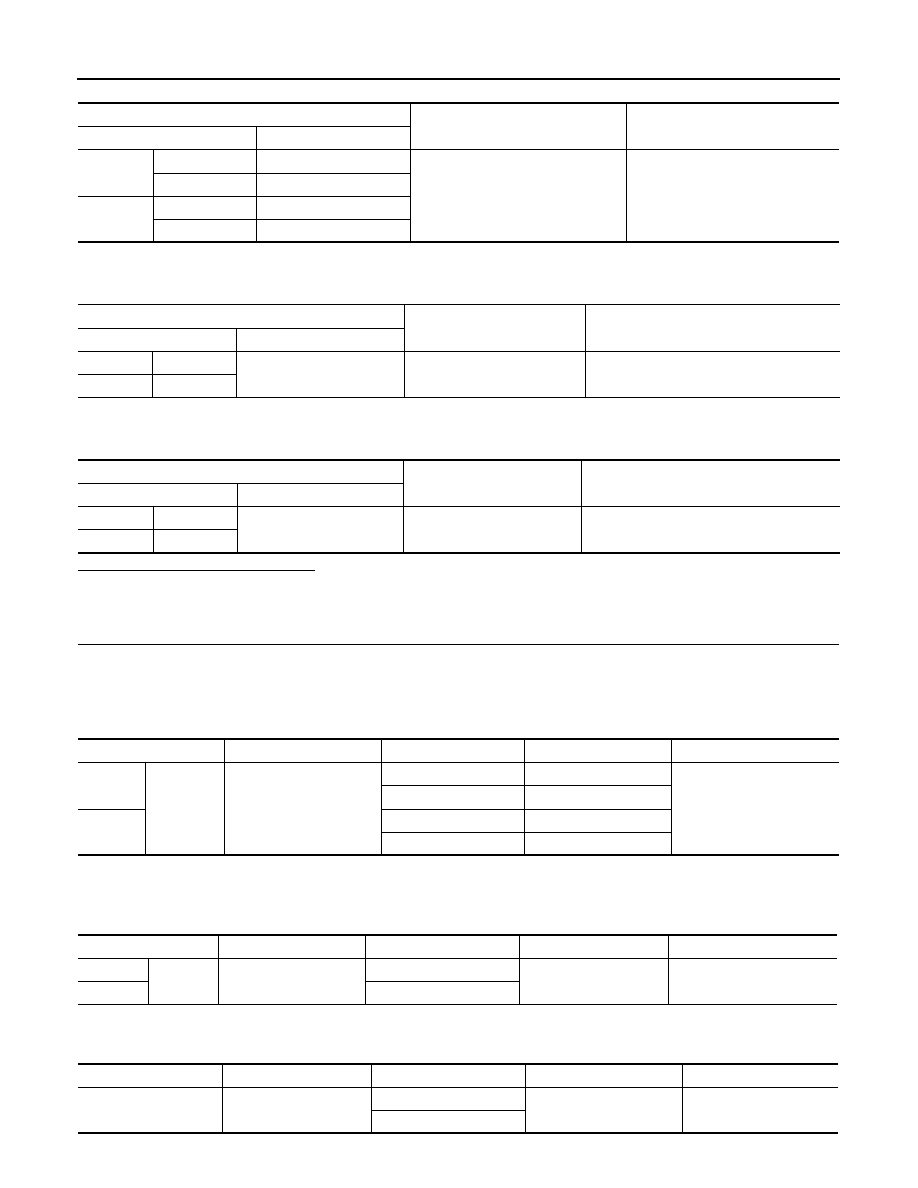
6. With the parking lamps ON, check voltage between the rear combination lamp connectors and ground.

7. With the parking lamps ON, check voltage between the license plate lamp connector and ground.

Are the inspection results normal?

YES

>> GO TO 5.

NO

>> GO TO 4.

4.

CHECK PARKING, LICENSE PLATE AND TAIL LAMP CIRCUIT (OPEN)

1. Turn the ignition switch OFF.

2. Disconnect IPDM E/R connector.

3. Check continuity between the IPDM E/R harness connector and the front combination lamp harness con-

nector.

4. Check continuity between the IPDM E/R harness connector and the rear combination lamp harness con-

nector.

5. Check continuity between the IPDM E/R harness connector and license plate lamp connector. 

(+)

(

−)

Voltage

Connector

Terminal

LH

E27

7

Ground

Battery voltage

E29

5

RH

E28

7

E30

5

(+)

(

−)

Voltage

Connector

Terminal

LH

B25

1

Ground

Battery voltage

RH

B27

(+)

(

−)

Voltage

Connector

Terminal

LH

D507

1

Ground

Battery voltage

RH

D508

Connector

Terminal

Connector

Terminal

Continuity

LH

E45

23

E27

7

Yes

E29

5

RH

E28

7

E30

5

Connector

Terminal

Connector

Terminal

Continuity

LH

E45

23

B25

1

Yes

RH

B27

Connector

Terminal

Connector

Terminal

Continuity

E45

23

D507

1

Yes

D508

PARKING LAMP CIRCUIT

EXL-81

< DTC/CIRCUIT DIAGNOSIS >

C

D

E

F

G

H

I

J

K

M

A

B

EXL

N

O

P

Are the inspection results normal?

YES

>> Replace IPDM E/R. Refer to 

PCS-31, "Removal and Installation"

 (with Intelligent Key) or 

PCS-60,

"Removal and Installation"

 (without Intelligent Key).

NO

>> Repair or replace the harness or connector.

5.

CHECK PARKING, LICENSE AND TAIL LAMP GROUND CIRCUITS

1. Check continuity between the front combination lamp harness connectors and ground.

2. Check continuity between the rear combination lamp harness connectors and ground.

3. Check continuity between the license plate lamp harness connectors and ground.

Are the inspection results normal?

YES

>> Replace the malfunctioning lamp.

NO

>> Repair or replace the harness or connector.

Connector

Terminal

Continuity

LH

E27

8

Ground

Yes

E29

6

RH

E28

8

E30

6

Connector

Terminal

Continuity

LH

B25

6

Ground

Yes

RH

B27

Connector

Terminal

Continuity

B507

2

Ground

Yes

B508

EXL-82

< DTC/CIRCUIT DIAGNOSIS >

TURN SIGNAL LAMP CIRCUIT

TURN SIGNAL LAMP CIRCUIT

Description

INFOID:0000000009694069

The BCM monitors inputs from the combination switch (high beam and turn signal switch) to determine when

to activate the turn signals. The BCM outputs voltage direction to the left and right turn signals during turn sig-

nal operation or both during hazard warning operation. The BCM sends a turn signal indicator request to the

combination meter via the CAN communication lines. 

The BCM performs the fast flasher operation (fail-safe) if any bulb or harness of the turn signal lamp circuit is

open.

NOTE:

Turn signal lamp blinks at normal speed when using the hazard warning lamp.

Component Function Check

INFOID:0000000009694070

1.

CHECK TURN SIGNAL LAMP

CONSULT

1. Select FLASHER of BCM (FLASHER) active test item.

2. While operating the test items, check that the turn signal lamp blinks.

Does the turn signal lamp blink?

YES

>> Turn signal lamp circuit is normal.

NO

>> Refer to 

EXL-82, "Diagnosis Procedure"

.

Diagnosis Procedure

INFOID:0000000009694071

Regarding Wiring Diagram information, refer to 

EXL-44, "Wiring Diagram"

.

1.

CHECK TURN SIGNAL LAMP BULB

Check the applicable lamp bulb to be sure the proper bulb standard is in use and the bulb is not open.
Is the bulb OK?

YES

>> GO TO 2.

NO

>> Replace the bulb.

2.

CHECK TURN SIGNAL LAMP OUTPUT VOLTAGE

1. Turn the ignition switch OFF.

2. Disconnect the front combination lamp connector and the rear combination lamp connector.

3. Turn the ignition switch ON.

4. With turn signal switch operating, check the voltage between the front combination lamp harness connec-

tor and ground.

LH

: Turn signal lamp LH blinking 

RH

: Turn signal lamp RH blinking 

OFF

: The turn signal lamp OFF

(+)

(

−)

Voltage

Connector

Terminal

LH

E29

4

Ground

RH

E30

4

PKID0926E

TURN SIGNAL LAMP CIRCUIT

EXL-83

< DTC/CIRCUIT DIAGNOSIS >

C

D

E

F

G

H

I

J

K

M

A

B

EXL

N

O

P

5. With turn signal switch operating, check the voltage between the rear combination lamp harness connec-

tor and ground.

Are the inspection results normal?

YES

>> GO TO 5.

NO

>> GO TO 3.

3.

CHECK TURN SIGNAL LAMP CIRCUIT FOR OPEN 

1. Turn the ignition switch OFF.

2. Disconnect BCM connector.

3. Check continuity between the BCM harness connector and the front combination lamp connector.

4. Check continuity between the BCM harness connector and the rear combination lamp connector. 

Are the inspection results normal?

YES

>> GO TO 4.

NO

>> Repair or replace the harness or connector.

4.

CHECK TURN SIGNAL LAMP SHORT CIRCUIT

Check continuity between the BCM harness connector and ground.

(+)

(

−)

Voltage

Connector

Terminal

LH

B25

4

Ground

RH

B27

4

PKID0926E

Connector

Terminal

Connector

Terminal

Continuity

Front LH

M99  (With Intelligent Key)

60

E29

4

Yes

Front RH

61

E30

Front LH

M19 (Without Intelligent Key)

64

E29

Front RH

63

E30

Connector

Terminal

Connector

Terminal

Continuity

Rear LH

M99  (With Intelligent Key)

60

B25

4

Yes

Rear RH

61

B27

Rear LH

M19 (Without Intelligent Key)

64

B25

Rear RH

63

B27

Connector

Terminal

Continuity

LH

M99 (With Intelligent Key)

60

Ground

No

RH

61

LH

M19 (Without Intelligent Key)

64

RH

63


Content   ..  422  423  424  425   ..