Nissan Versa Note. Manual - part 398
EM-108
< UNIT DISASSEMBLY AND ASSEMBLY >
[HR16DE]
CYLINDER BLOCK
CAUTION:
Do not rotate crankshaft.
• Remove main bearing cap and bearings, and using the scale (A)
on the plastigage bag, measure the plastigage width.
NOTE:
The procedure when the measured value exceeds the limit is
same as that described in the “Method by Calculation”.
MAIN BEARING CRUSH HEIGHT
• When main bearing cap is removed after being tightened to the
specified torque with main bearings (1) installed, the tip end of
bearing must protrude (B). Refer to
• If the standard is not met, replace main bearings.
CONNECTING ROD BEARING CRUSH HEIGHT
• When connecting rod cap is removed after being tightened to the
specified torque with connecting rod bearings (1) installed, the tip
end of bearing must protrude (B). Refer to
.
• If the standard is not met, replace connecting rod bearings.
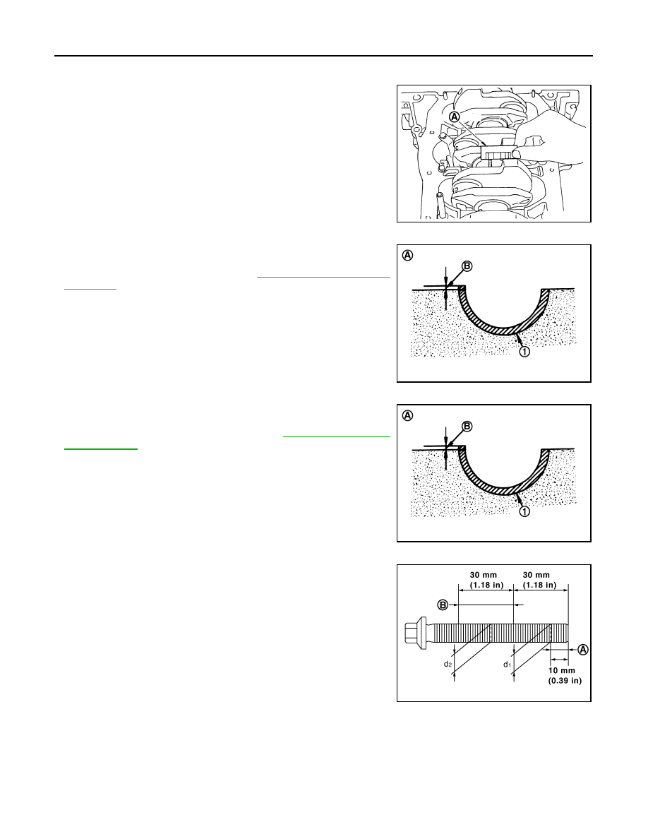
MAIN BEARING CAP BOLT OUTER DIAMETER
• Measure the outer diameters (d
1
) and (d
2
) at two positions as
shown.
• If reduction appears in places other than (B) range, regard it as
(d
2
).
• If it exceeds the limit (a large difference in dimensions), replace
main bearing cap bolt with a new one.
CONNECTING ROD CAP BOLT OUTER DIAMETER
PBIC3278J
(A)
: Example
Standard
: There must be crush height.
PBIC3279J
(A)
: Example
Standard
: There must be crush height.
PBIC3279J
(A)
: (d1) measuring position
(B)
: (d2) measuring position
Limit [(d
1
) – (d
2
)]: 0.2 mm (0.0078 in)
PBIC4015E