Nissan Versa Note. Manual - part 393


  Index      Nissan     Nissan Versa Note (2014 year) - Service and Repair Manual


Search            


Content   ..  391  392  393  394   ..


Nissan Versa Note. Manual - part 393


EM-88

< UNIT REMOVAL AND INSTALLATION >

[HR16DE]

ENGINE ASSEMBLY

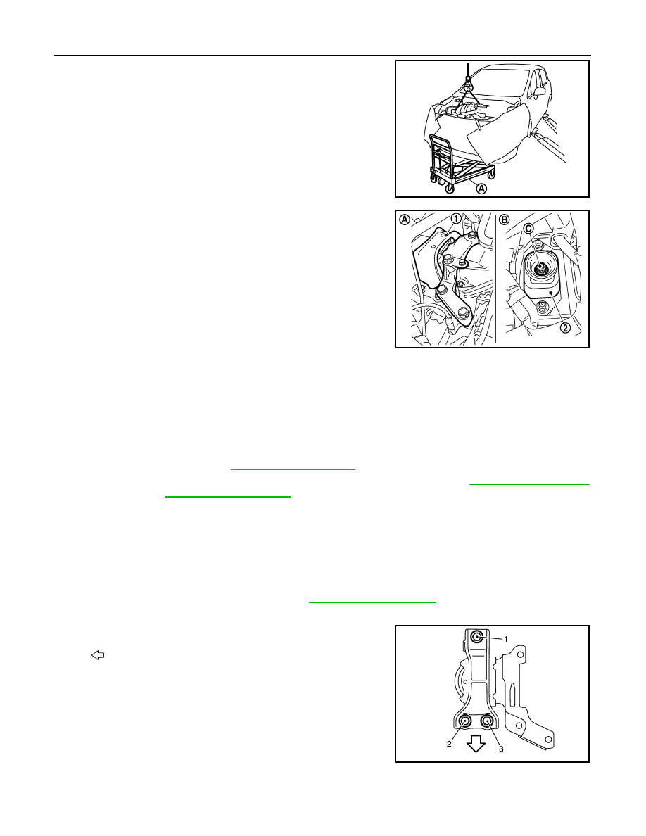
22. Use a suitable jack (A) to securely support the bottom of the

engine and the transaxle assembly.

CAUTION:

Put a piece of wood or an equivalent as the supporting sur-

face and secure in a stable condition.

23. Remove engine mounting insulator (RH) (1).

24. Remove engine through bolt-securing nut (C).

25. Carefully lower suitable jack, or raise lift to remove the engine and the transaxle assembly. Observe the

following cautions:

CAUTION:

• Check that no part interferes with the vehicle side.

• Before and during lifting, always check if any harnesses are left connected.

• During removal, always be careful to prevent the vehicle from falling off the lift due to changes in

the center of gravity.

• If necessary, support the vehicle by setting jack or suitable tool at the rear.

26. Remove starter motor. Refer to 

STR-31, "Exploded View"

.

27. Lift with a hoist and separate the engine from the transaxle assembly. Refer to 

TM-24, "Exploded View"

(M/T models) and 

TM-252, "Exploded View"

 (CVT models).

INSTALLATION

Installation is in the reverse order of removal.

CAUTION:

• Do not allow engine oil to get on engine mounting insulator. Be careful not to damage engine mount-

ing insulator.

• Check that each mounting insulator is seated properly, and tighten nuts and bolts.

• When installation directions are specified, install parts according to the direction marks on them,

referring to the figure of components. Refer to 

EM-85, "Exploded View"

.

Engine Mounting Insulator (RH)

• Tighten bolts in the numerical order as shown.

INSPECTION AFTER INSTALLATION

PBIC3223J

(2)

: Engine mounting insulator (LH)

(A)

: Engine front side

(B)

: Transaxle side

JSBIA1223ZZ

: Front

JPBIA2809ZZ

ENGINE ASSEMBLY

EM-89

< UNIT REMOVAL AND INSTALLATION >

[HR16DE]

C

D

E

F

G

H

I

J

K

L

M

A

EM

N

P

O

• Before starting engine, check oil/fluid levels including engine coolant and engine oil. If less than required

quantity, fill to the specified level. Refer to 

MA-11, "Fluids and Lubricants"

.

• Use procedure below to check for fuel leaks.

• Turn ignition switch ON (with engine stopped). With fuel pressure applied to fuel piping, check for fuel leaks

at connection points.

• Start engine. With engine speed increased, check again for fuel leaks at connection points.

• Run engine to check for unusual noise and vibration.

NOTE:

If hydraulic pressure inside timing chain tensioner drops after removal and installation, slack in the guide

may generate a pounding noise during and just after engine start. However, this is normal. Noise will stop

after hydraulic pressure rises.

• Warm up engine thoroughly to make sure there are no leaks of fuel, exhaust gas, or any oils/fluids including

engine oil and engine coolant.

• Bleed air from passages in lines and hoses, such as in cooling system.

• After cooling down engine, again check oil/fluid levels including engine oil and engine coolant. Refill to spec-

ified level, if necessary.

• Summary of the inspection items:

*Power steering fluid, brake fluid, etc.

Item

Before starting engine

Engine running

After engine stopped

Engine coolant

Level

Leaks

Level

Engine oil

Level

Leaks

Level

Transmission/
transaxle fluid 

CVT Models

Leaks

Level/Leaks

Leaks

M/T Models

Level/Leaks

Leaks

Level/Leaks

Other oils and fluids*

Level

Leaks

Level

Fuel

Leaks

Leaks

Leaks

Exhaust gas

Leaks

EM-90

< UNIT DISASSEMBLY AND ASSEMBLY >

[HR16DE]

ENGINE UNIT

UNIT DISASSEMBLY AND ASSEMBLY

ENGINE UNIT

Setting

INFOID:0000000009444748

NOTE:

The following procedures explain how to disassemble the engine with the engine stand fastened to the bell

housing. Some steps may be different if using a different type of engine stand.
1. Install engine to engine stand:
a. On (M/T models), remove flywheel. 

• Secure flywheel (1) using suitable tool (A) and remove bolts.

CAUTION:

• Do not disassemble flywheel.

• Do not place flywheel with signal plate facing down.

• When handling signal plate, take care not to damage or

scratch it. 

• Handle signal plate in a manner that prevents it from

becoming magnetized.

b. On (CVT models), remove driveplate.

• Secure driveplate (1) using suitable tool (A) and remove bolts. 

CAUTION:

• Do not disassemble flywheel.

• Do not place flywheel or drive plate with signal plate fac-

ing down.

• When handling signal plate, take care not to damage or

scratch it. 

• Handle signal plate in a manner that prevents it from

becoming magnetized.

c.

Lift the engine with a hoist to install it onto a widely used engine stand.

CAUTION:

• Use the engine stand that has a load capacity approximately 150 kg (331 lb) or more large

enough for supporting the engine weight. 

• If the load capacity of stand is not adequate, remove the following parts beforehand to reduce the poten-

tial risk of overturning stand.

- Intake manifold. Refer to 

EM-28, "Exploded View"

- Exhaust manifold. Refer to 

EM-31, "Removal and Installation"

.

- Rocker cover. Refer to 

EM-48, "Exploded View"

.

NOTE:

The figure shows an example of widely used engine stand (A)

that can support the mating surface of transaxle with flywheel

removed.

CAUTION:

Before removing the hanging chains, check the engine

stand is stable and there is no risk of overturning.

2. Drain engine oil. Refer to 

LU-8, "Draining"

.

CAUTION:

Tool number

: KV11105210 (J-44716)

MBIB1382E

Tool number

: KV11105210 (J-44716)

MBIB1382E

PBIC3227J

ENGINE UNIT

EM-91

< UNIT DISASSEMBLY AND ASSEMBLY >

[HR16DE]

C

D

E

F

G

H

I

J

K

L

M

A

EM

N

P

O

• Be sure to clean drain plug and install with new drain plug washer.

• Do not reuse drain plug washer.

3. Drain engine coolant by removing water drain plug (1) from

inside of the engine. 

Use Genuine Silicone RTV Sealant or equivalent. Refer to

GI-22, "Recommended Chemical Products and Sealants"

.

Disassembly

INFOID:0000000009444749

1. Remove intake manifold. Refer to 

EM-28, "Exploded View"

.

2. Remove exhaust manifold. Refer to 

EM-31, "Exploded View"

.

3. Remove oil pan (lower). Refer to 

EM-34, "Exploded View"

.

4. Remove ignition coil, spark plug, and rocker cover. Refer to 

EM-48, "Exploded View"

.

5. Remove fuel injector and fuel tube. Refer to 

EM-40, "Exploded View"

.

6. Remove front cover and timing chain. Refer to 

EM-51, "Exploded View"

.

7. Remove camshaft. Refer to 

EM-60, "Exploded View"

.

8. Remove cylinder head. Refer to 

EM-76, "Exploded View"

.

Assembly

INFOID:0000000009444750

Assembly is in the reverse order of disassembly.

: Engine front

Water drain plug 
tightening torque

: Refer to 

EM-92, "Exploded View"

.

AWBIA1607ZZ


Content   ..  391  392  393  394   ..