Nissan Versa Note. Manual - part 387


  Index      Nissan     Nissan Versa Note (2014 year) - Service and Repair Manual


Search            


Content   ..  385  386  387  388   ..


Nissan Versa Note. Manual - part 387


EM-64

< REMOVAL AND INSTALLATION >

[HR16DE]

CAMSHAFT

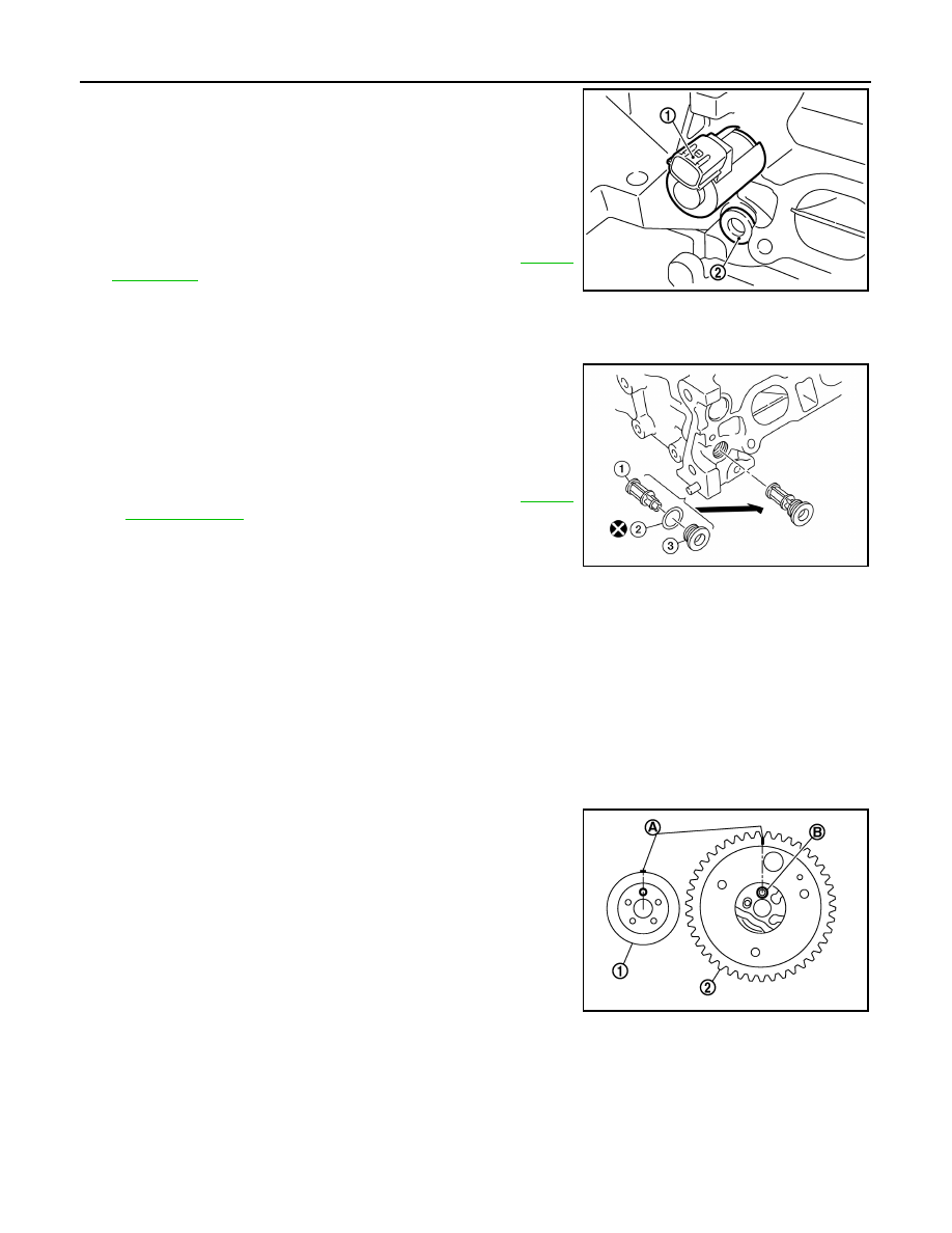
10. Remove the intake valve timing control solenoid valve (1) and

the plug (2) securing the oil filter for intake valve timing control

solenoid valve.

11. Remove the exhaust valve timing control solenoid valve.
12. Remove the plug on the exhaust valve timing control solenoid

valve.

13. Remove the oil filter for exhaust valve timing control solenoid

valve.

14. For component inspection after removal, refer to 

EM-68,

"Inspection"

.

INSTALLATION

CAUTION:

Do not reuse O-rings or washers.
1. Install oil filter (1) for intake and exhaust valve timing control

solenoid valves.

CAUTION:

Do not reuse washers.

NOTE:

The intake side is shown as an example.

• The oil filter (1) and washer (2) are assembled to the plug (3),

and then install them in to the cylinder head. Refer to 

EM-60,

"Exploded View"

.

2. Install intake and exhaust valve timing control solenoid valves.

• Insert it straight into the cylinder head.

• Tighten bolts.

CAUTION:

Do not reuse O-rings.

3. Install valve lifters.

• If they are reused, install them in the original positions.

4. Put a matching mark for positioning the camshaft (INT) and the camshaft sprocket (INT): 

NOTE:

This helps prevent the knock pin from engaging with the incorrect pin hole after installing the camshaft

(INT) and the camshaft sprocket (INT).

a. Put the matching marks (A) on a line extending from the knock

pin position of camshaft (INT) (1) front surface.

• Put the marks on the visible position with the camshaft

sprocket installed as shown. 

b. Put the matching marks on a line extending from the knock pin

hole (B) position of camshaft sprocket (INT) (2) as shown. 

• Put the marks on the visible position with it installed to the

camshaft.

5. Put a matching mark for positioning the camshaft (EXH) and the camshaft sprocket (EXH):

NOTE:

This helps prevent the knock pin from engaging with the incorrect pin hole after installing the camshaft

(INT) and the camshaft sprocket (EXH).

PBIC3692E

AWBIA1146GB

PBIC3696E

CAMSHAFT

EM-65

< REMOVAL AND INSTALLATION >

[HR16DE]

C

D

E

F

G

H

I

J

K

L

M

A

EM

N

P

O

a. Put the matching marks (A) on a line extending from the knock

pin position of camshaft (EXH) (1) front surface.

• Put the marks on the visible position with the camshaft

sprocket installed as shown. 

b. Put the matching marks on a line extending from the knock pin

hole (B) position of camshaft sprocket (EXH) (2) as shown. 

• Put the marks on the visible position with it installed to the

camshaft.

6. Install camshaft.

• Note that the camshafts (INT and EXH) have different shapes

at the rear.

• Install camshafts to the cylinder head so that knock pins (A) on

front end are positioned as shown.

NOTE:

Though camshaft does not stop at the portion as shown for the

placement of cam nose, it is generally accepted camshaft is

placed for the same direction as shown.

7. Install camshaft brackets (2 to 5) and (A to D).

JPBIA4155ZZ

(1) : Camshaft (EXH)
(2) : Camshaft (INT)
(A) : Identification mark

Indentification Color

M1 (A)

Camshaft (EXH)

Yellow - Green x 2

Camshaft (INT)

White

JPBIA4156ZZ

(1) : Camshaft (EXH)
(2) : Camshaft (INT)

: Upper side

JPBIA4157ZZ

(A) : EXH side (2 to 5)
(B) : INT side (A to D)

: Engine front

PBIC3703E

EM-66

< REMOVAL AND INSTALLATION >

[HR16DE]

CAMSHAFT

8. Tighten bolts of camshaft brackets in the following steps, in

numerical order as shown.

a. Tighten No. 9 to 11 in numerical order.

b. Tighten No. 1 to 8 in numerical order.

c.

Tighten all bolts in numerical order.

d. Tighten all bolts in numerical order.

9. Install the camshaft sprocket (INT/EXH) to the camshaft (INT/EXH): 
a. Refer to the matching mark (A) added in step 4. Securely align

the knock pin and the pin hole, and then install them.

NOTE:

The intake side is shown as an example.

10. Tighten the camshaft sprocket bolt (INT/EXH).

CAUTION:

Hold the camshaft hexagonal part (A), using a suitable tool

to secure the camshaft.

11. Align the matching mark (peripheral groove) (A/C) and the pink

link (B) on the timing chain.

• If the positions of knock pin and pin groove are not aligned,

move the camshaft (EXH) slightly to correct these positions.

(A) : EXH side
(B) : INT side

: Engine front

Camshaft bracket bolts

: 1.96 N·m (0.20 kg-m, 17 in-lb)

Camshaft bracket bolts

: 1.96 N·m (0.20 kg-m, 17 in-lb)

Camshaft bracket bolts

: 5.88 N·m (0.60 kg-m, 52 in-lb)

Camshaft bracket bolts

: 10.4 N·m (1.1 kg-m, 8 ft-lb)

PBIC3686E

PBIC3700E

(1) : Camshaft sprocket (INT)

JPBIA4158ZZ

(1) : Timing chain
(2) : Camshaft sprocket (EXH)
(3) : Camshaft sprocket (INT)

JPBIA4159ZZ

CAMSHAFT

EM-67

< REMOVAL AND INSTALLATION >

[HR16DE]

C

D

E

F

G

H

I

J

K

L

M

A

EM

N

P

O

12. Pull out the stopper pin (A), and then apply the tension to the

timing chain by rotating the crankshaft pulley clockwise slightly.

13. Pull out the stopper pin of chain tensioner.
14. Install front cover.
15. Return the camshaft sprocket (INT) in the most retarded position:
a. Remove the stopper pin (A) from the camshaft sprocket (INT).

b. Turn the crankshaft pulley (1) slowly clockwise (A) and return

the camshaft sprocket (INT) to the most retarded angle position.

• When first turning the crankshaft, the camshaft sprocket (INT)

will turn. Once it is turned more, and the vane (camshaft) also

turns, then it has reached the most retarded angle position.

• The most retarded angle position can be checked by seeing if

the stopper pin groove (A) is shifted clockwise.

• After spinning the crankshaft slightly in the counterclockwise

direction, you can check the lock pin has joined by seeing if

the vane (camshaft) and the sprocket move together.

16. Install the camshaft position sensor (PHASE) to the rear end of cylinder head.

• Tighten bolts with it completely inserted.

17. Check and adjust valve clearance. Refer to 

EM-10, "Inspection and Adjustment"

.

18. Installation of the remaining components is in the reverse order of removal.

INSPECTION AFTER INSTALLATION

(1) : Plunger
(2) : Chain tensioner
(B) : Lever
(C) : Lever hole
(D) : Front cover has been removed for clarity.

PBIC3772E

(B) : Tape

PBIC3685E

PBIC3704E

(B) : Stopper pin hole
(C) : Most advanced angle
(D) : Lock pin engaged 

PBIC3705E


Content   ..  385  386  387  388   ..