Nissan Versa Note. Manual - part 361
EC-426
< DTC/CIRCUIT DIAGNOSIS >
[HR16DE]
ASCD BRAKE SWITCH
YES
>> GO TO 3.
NO
>> Repair or replace error-detected parts.
3.
CHECK ASCD BRAKE SWITCH
Check the ASCD brake switch. Refer to
EC-426, "Component Inspection (ASCD Brake Switch)"
Is the inspection result normal?
YES
>> Check intermittent incident. Refer to
GI-41, "Intermittent Incident"
.
NO
>> Replace ASCD brake switch. Refer to
Component Inspection (ASCD Brake Switch)
INFOID:0000000009020918
1.
CHECK ASCD BRAKE PEDAL POSITION SWITCH-I
1. Turn ignition switch OFF.
2. Disconnect ASCD brake switch harness connector.
3. Check the continuity between ASCD brake switch terminals as per the following conditions.
Is the inspection result normal?
YES
>> INSPECTION END
NO
>> GO TO 2.
2.
CHECK ASCD BRAKE SWITCH-II
1. Adjust ASCD brake switch installation. Refer to
BR-20, "Inspection and Adjustment"
2. Check the continuity between ASCD brake switch terminals as per the following conditions.
Is the inspection result normal?
YES
>> INSPECTION END
NO
>> Replace ASCD brake switch. Refer to
.
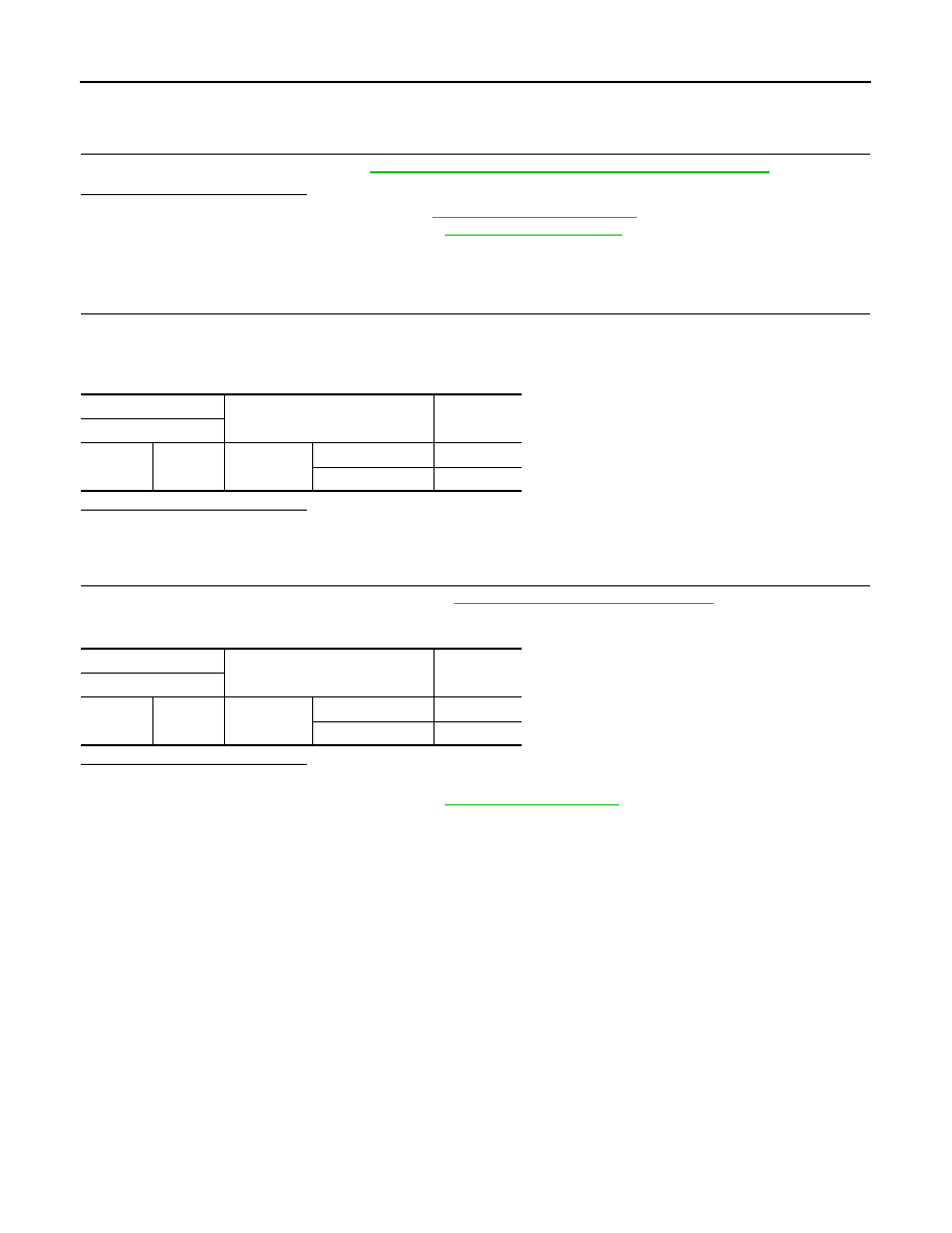
ASCD brake switch
Condition
Continuity
Terminal
1
2
Brake pedal
Fully released
Existed
Slightly depressed
Not existed
ASCD brake switch
Condition
Continuity
Terminal
1
2
Brake pedal
Fully released
Existed
Slightly depressed
Not existed