Nissan Versa Note. Manual - part 355
EC-402
< DTC/CIRCUIT DIAGNOSIS >
[HR16DE]
P2100, P2103 THROTTLE CONTROL MOTOR RELAY
2.
CHECK THROTTLE CONTROL MOTOR RELAY INPUT SIGNAL CIRCUIT-I
1. Disconnect ECM harness connector.
2. Disconnect IPDM E/R harness connector F115.
3. Check the continuity between ECM harness connector and IPDM E/R harness connector.
4. Also check harness for short to ground and short to power.
Is the inspection result normal?
YES
>> GO TO 4.
NO
>> GO TO 3.
3.
DETECT MALFUNCTIONING PART
Check the following.
• IPDM E/R connector F42
• Harness for open or short between IPDM E/R and ECM
>> Repair open circuit or short to ground or short to power in harness or connectors.
4.
CHECK FUSE
1. Disconnect 20 A fuse (No. 53) from IPDM E/R.
2. Check 20 A fuse for blown.
Is the inspection result normal?
YES
>> GO TO 9.
NO
>> Replace 20 A fuse.
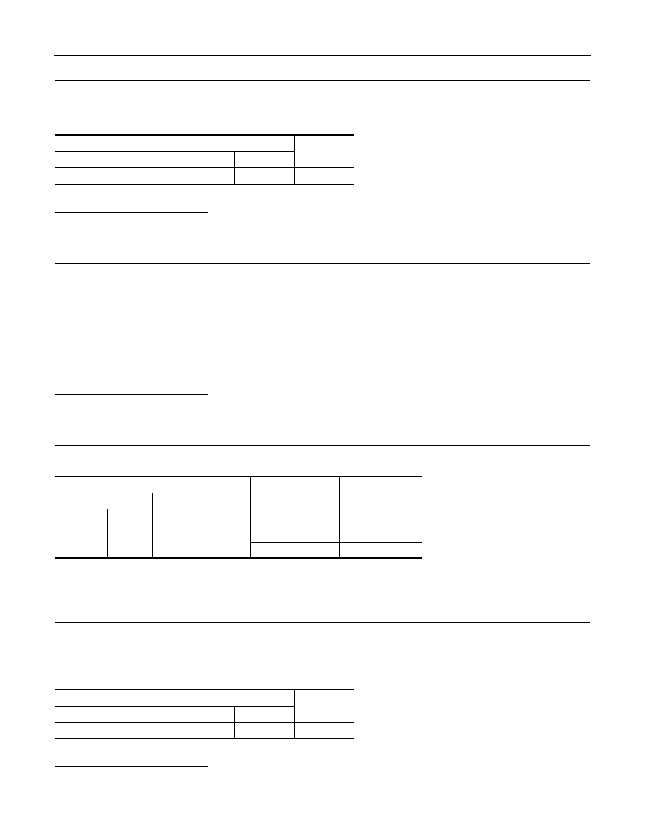
5.
CHECK THROTTLE CONTROL MOTOR RELAY INPUT SIGNAL CIRCUIT-I
1. Check voltage between ECM harness connector and ground under the following conditions.
Is the inspection result normal?
YES
>> GO TO 8.
NO
>> GO TO 6.
6.
CHECK THROTTLE CONTROL MOTOR RELAY INPUT SIGNAL CIRCUIT-II
1. Turn ignition switch OFF.
2. Disconnect ECM harness connector.
3. Disconnect IPDM E/R harness connector F42.
4. Check the continuity between ECM harness connector and IPDM E/R harness connector.
5. Also check harness for short to ground and short to power.
Is the inspection result normal?
YES
>> GO TO 8.
NO
>> GO TO 7.
ECM
IPDM E/R
Continuity
Connector
Terminal
Connector
Terminal
F10
15
F42
32
Existed
ECM
Conditions
Voltage
+
−
Connector
Terminal
Connector
Terminal
F10
2
E16
108
Ignition switch: OFF
Approx. 0 V
Ignition switch: ON
Battery voltage
ECM
IPDM E/R
Continuity
Connector
Terminal
Connector
Terminal
F10
2
F42
29
Existed