Nissan Versa Note. Manual - part 261


  Index      Nissan     Nissan Versa Note (2014 year) - Service and Repair Manual


Search            


Content   ..  259  260  261  262   ..


Nissan Versa Note. Manual - part 261


EC-26

< SYSTEM DESCRIPTION >

[HR16DE]

COMPONENT PARTS

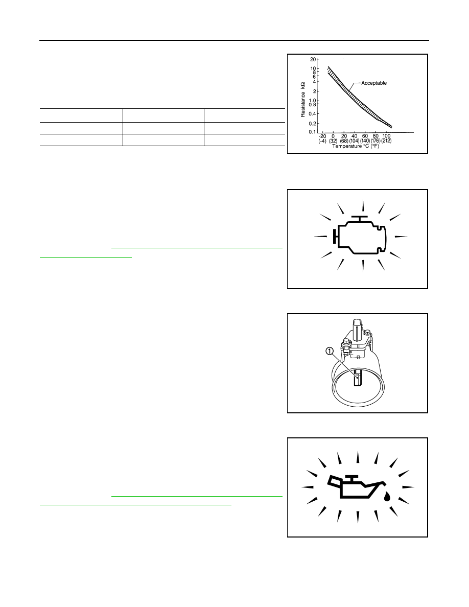
BATTERY TEMPERATURE SENSOR

Battery temperature sensor is integrated in battery current sensor.

The sensor measures temperature around the battery.

The electrical resistance of the thermistor decreases as temperature

increases.

<Reference data>

*: These data are reference values and are measured between battery temperature
sensor signal terminal and sensor ground.

Malfunction Indicator Lamp (MIL)

INFOID:0000000009020596

The MIL is located on the combination meter.

The MIL will illuminate when the ignition switch is turned ON without

the engine running. This is a bulb check.

When the engine is started, the MIL should turn OFF. If MIL remains

ON or continues blinking, the on board diagnostic system detects a

DTC(s) that affects exhaust gas.

For details, refer to 

EC-57, "DIAGNOSIS DESCRIPTION : Malfunc-

tion Indicator Lamp (MIL)"

.

Mass Air Flow Sensor

INFOID:0000000009020597

The mass air flow sensor (1) is placed in the stream of intake air. It

measures the intake flow rate by measuring a part of the entire

intake flow. The mass air flow sensor controls the temperature of the

hot wire to a certain amount. The heat generated by the hot wire is

reduced as the intake air flows around it. The more air, the greater

the heat loss. 

Therefore, the electric current supplied to hot wire is changed to

maintain the temperature of the hot wire as air flow increases. The

ECM detects the air flow by means of this current change.

Oil Pressure Warning Lamp

INFOID:0000000009020598

Oil pressure warning lamp is located on the combination meter. 

It indicates the low pressure of the engine oil and the malfunction of

the engine oil pressure system. 

Combination meter turns the oil pressure warning lamp ON/OFF

according to the oil pressure warning lamp signal received from

ECM via CAN communication.

For details, refer to 

EC-43, "ENGINE PROTECTION CONTROL AT

LOW ENGINE OIL PRESSURE : System Description"

.

Temperature [

°C (°F)]

Voltage

*

 (V)

Resistance (k

Ω)

25 (77)

3.333

1.9 - 2.1

90 (194)

0.969

0.222 - 0.258

SEF012P

SAT652J

PBIA9559J

PBIA8559J

COMPONENT PARTS

EC-27

< SYSTEM DESCRIPTION >

[HR16DE]

C

D

E

F

G

H

I

J

K

L

M

A

EC

N

P

O

Refrigerant Pressure Sensor

INFOID:0000000009020599

The refrigerant pressure sensor is installed at the condenser of the air conditioner system. The sensor uses an

electrostatic volume pressure transducer to convert refrigerant pressure to voltage. The voltage signal is sent

to ECM, and ECM controls cooling fan system.

Stop Lamp Switch & ASCD Brake Switch

INFOID:0000000009020600

Stop lamp switch and ASCD brake switch are installed to brake pedal bracket.

ECM detects the state of the brake pedal by those two types of input (ON/OFF signal).

Throttle Control Motor

INFOID:0000000009020601

The throttle control motor is operated by the ECM and it opens and closes the throttle valve.

The current opening angle of the throttle valve is detected by the throttle position sensor and it provides feed-

back to the ECM to control the throttle valve in response to driving conditions via the throttle control motor.

Throttle Control Motor Relay

INFOID:0000000009020602

Power supply for the throttle control motor is provided to the ECM via throttle control motor relay. The throttle

control motor relay is ON/OFF controlled by the ECM. When the ignition switch is turned ON, the ECM sends

an ON signal to throttle control motor relay and battery voltage is provided to the ECM. When the ignition

switch is turned OFF, the ECM sends an OFF signal to throttle control motor relay and battery voltage is not

provided to the ECM.

Throttle Position Sensor

INFOID:0000000009020603

Electric throttle control actuator consists of throttle control motor,

throttle position sensor, etc. The throttle position sensor responds to

the throttle valve movement. 

The throttle position sensor has two sensors. These sensors are a

kind of potentiometer which transform the throttle valve position into

output voltage, and emit the voltage signals to the ECM. The ECM

judges the current opening angle of the throttle valve from these sig-

nals and controls the throttle valve in response to driving conditions

via the throttle control motor.

ASCD Steering Switch

INFOID:0000000009020604

ASCD steering switch has variant values of electrical resistance for each button. ECM reads voltage variation

of switch, and determines which button is operated.

PBIB2657E

Brake pedal

ASCD brake switch

Stop lamp switch

Released

ON

OFF

Depressed

OFF

ON

PBIB0145E

EC-28

< SYSTEM DESCRIPTION >

[HR16DE]

STRUCTURE AND OPERATION

STRUCTURE AND OPERATION

Positive Crankcase Ventilation

INFOID:0000000009020605

This system returns blow-by gas to the intake manifold.

The positive crankcase ventilation (PCV) valve is provided to conduct crankcase blow-by gas to the intake

manifold.

During partial throttle operation of the engine, the intake manifold sucks the blow-by gas through the PCV

valve.

Normally, the capacity of the valve is sufficient to handle any blow-by and a small amount of ventilating air.

The ventilating air is then drawn from the air inlet tubes into the crankcase. In this process the air passes

through the hose connecting air inlet tubes to rocker cover.

Under full-throttle condition, the manifold vacuum is insufficient to draw the blow-by flow through the valve.

The flow goes through the hose connection in the reverse direction.

On vehicles with an excessively high blow-by, the valve does not

meet the requirement. This is because some of the flow will go

through the hose connection to the air inlet tubes under all condi-

tions.

PBIB2962E

PBIB1588E

STRUCTURE AND OPERATION

EC-29

< SYSTEM DESCRIPTION >

[HR16DE]

C

D

E

F

G

H

I

J

K

L

M

A

EC

N

P

O

On Board Refueling Vapor Recovery (ORVR)

INFOID:0000000009020606

From the beginning of refueling, the air and vapor inside the fuel tank go through refueling EVAP vapor cut

valve and EVAP/ORVR line to the EVAP canister. The vapor is absorbed by the EVAP canister and the air is

released to the atmosphere.

When the refueling has reached the full level of the fuel tank, the refueling EVAP vapor cut valve is closed and

refueling is stopped because of auto shut-off. The vapor which was absorbed by the EVAP canister is purged

during driving.

WARNING:

When conducting inspections below, be sure to observe the following:

• Put a “CAUTION: FLAMMABLE” sign in workshop.

• Do not smoke while servicing fuel system. Keep open flames and sparks away from work area.

• Be sure to furnish the workshop with a CO

2

 fire extinguisher.

CAUTION:

• Before removing fuel line parts, carry out the following procedures:

- Put drained fuel in an explosion-proof container and put lid on securely.

- Release fuel pressure from fuel line. Refer to 

EC-135, "Work Procedure"

.

- Disconnect battery ground cable.

• Always replace O-ring when the fuel gauge retainer is removed.

• Do not kink or twist hose and tube when they are installed.

• Do not tighten hose and clamps excessively to avoid damaging hoses.

• After installation, run engine and check for fuel leaks at connection.

• Do not attempt to top off the fuel tank after the fuel pump nozzle shuts off automatically.

Continued refueling may cause fuel overflow, resulting in fuel spray and possibly a fire.

JMBIA1930GB


Content   ..  259  260  261  262   ..