Nissan Versa Note. Manual - part 236
DOOR LOCK AND UNLOCK SWITCH
DLK-229
< DTC/CIRCUIT DIAGNOSIS >
[WITHOUT INTELLIGENT KEY SYSTEM]
C
D
E
F
G
H
I
J
L
M
A
B
DLK
N
O
P
3.
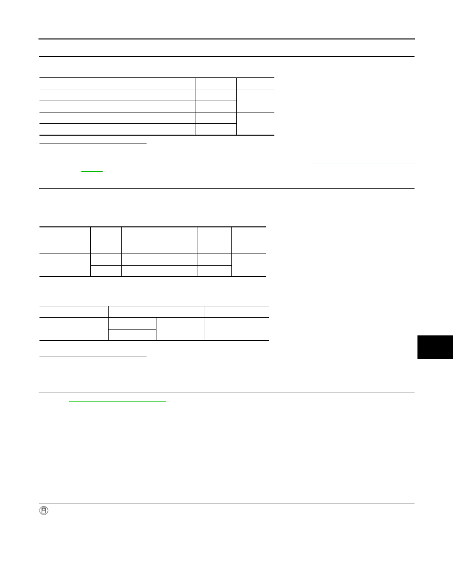
CHECK POWER WINDOW SWITCH
Check continuity between main power window and door lock/unlock switch terminals.
Is the inspection result normal?
YES
>> GO TO 4
NO
>> Replace main power window and door lock/unlock switch. Refer to
.
4.
CHECK POWER WINDOW SWITCH CIRCUITS
1. Disconnect BCM connector.
2. Check continuity between BCM connector and main power window and door lock/unlock switch connec-
tor.
3. Check continuity between BCM connector and ground.
Is the inspection result normal?
YES
>> GO TO 5
NO
>> Repair or replace harness.
5.
CHECK INTERMITTENT INCIDENT
GI-41, "Intermittent Incident"
.
>> Inspection End.
PASSENGER SIDE
PASSENGER SIDE : Description
INFOID:0000000009645378
Transmits door lock/unlock operation to BCM.
PASSENGER SIDE : Component Function Check
INFOID:0000000009645379
1.
CHECK FUNCTION
With CONSULT
Check CDL LOCK SW, CDL UNLOCK SW in Data Monitor mode with CONSULT.
Main power window and door lock/unlock switch state
Terminals
Continuity
Lock
17 - 18
Yes
Unlock
6 - 17
Neutral/Lock
6 - 17
No
Neutral/Unlock
17 - 18
BCM connector
Terminal
Main power window and
door lock/unlock switch
connector
Terminal
Continuity
M18
12
D8
18
Yes
13
D7
6
BCM connector
Terminal
Continuity
M18
12
Ground
No
13