Nissan Versa Note. Manual - part 196
B2623 INSIDE ANTENNA
DLK-69
< DTC/CIRCUIT DIAGNOSIS >
[WITH INTELLIGENT KEY SYSTEM]
C
D
E
F
G
H
I
J
L
M
A
B
DLK
N
O
P
1. Turn ignition switch OFF.
2. Disconnect BCM connector and inside key antenna (trunk room) connector.
3. Check continuity between BCM harness connector and inside key antenna (trunk room) harness connec-
tor.
4. Check continuity between BCM harness connector and ground.
Is the inspection result normal?
YES
>> GO TO 3.
NO
>> Repair or replace harness.
3.
CHECK INSIDE KEY ANTENNA INPUT SIGNAL 2
1. Replace inside key antenna (trunk room). (New antenna or other antenna)
2. Connect BCM connector and inside key antenna (trunk room) connector.
3. Turn ignition switch ON.
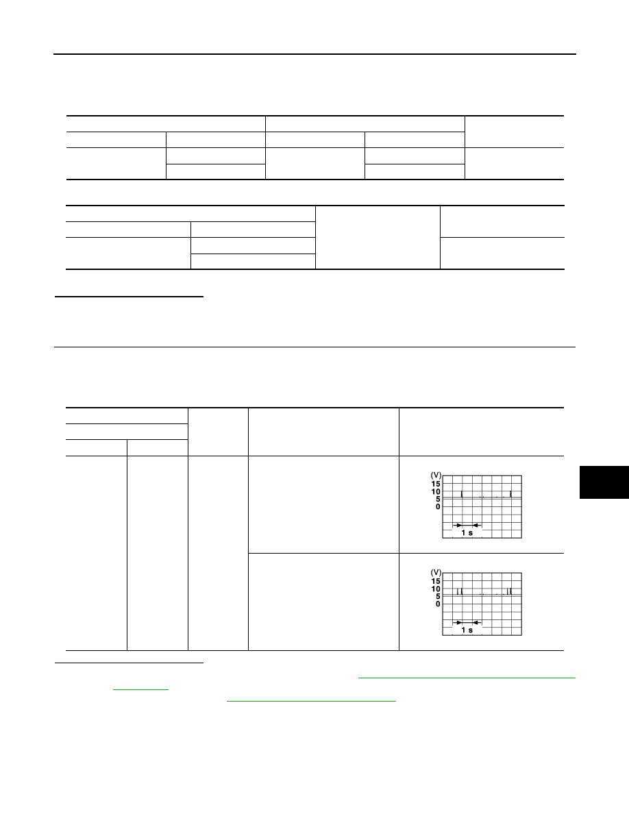
4. Check signal between BCM harness connector and ground using oscilloscope.
Is the inspection result normal?
YES
>> Replace inside key antenna (trunk room). Refer to
DLK-176, "LUGGAGE ROOM : Removal and
NO
>> Replace BCM. Refer to
BCS-70, "Removal and Installation"
BCM
Inside key antenna (trunk room)
Continuity
Connector
Terminal
Connector
Terminal
M98
88
B48
1
Yes
89
2
BCM
Ground
Continuity
Connector
Terminal
M98
88
No
89
(+)
(–)
Condition
Signal
(Reference value)
BCM
Connector
Terminal
M98
88
89
Ground
When Intelligent Key is in the anten-
na detection area
When Intelligent Key is not in the an-
tenna detection area
JMKIA3839GB
JMKIA5951GB