Nissan Versa Note. Manual - part 127
BRC-72
< DTC/CIRCUIT DIAGNOSIS >
[VDC/TCS/ABS]
C1121, C1123, C1125, C1127 ABS OUT VALVE SYSTEM
C1121, C1123, C1125, C1127 ABS OUT VALVE SYSTEM
DTC Logic
INFOID:0000000009637514
DTC DETECTION LOGIC
DTC CONFIRMATION PROCEDURE
1.
CHECK SELF DIAGNOSTIC RESULT
With CONSULT.
1. Turn ignition switch ON.
2. Perform self diagnostic result.
Is DTC C1121, C1123, C1125 or C1127 detected?
YES
>> Proceed to diagnosis procedure. Refer to
.
NO
>> Inspection End.
Diagnosis Procedure
INFOID:0000000009637515
Regarding Wiring Diagram information, refer to
1.
CONNECTOR INSPECTION
1. Turn ignition switch OFF.
2. Disconnect ABS actuator and electric unit (control unit) connector.
3. Check connector and terminals for deformation, disconnection, looseness or damage.
Is the inspection result normal?
YES
>> GO TO 2
NO
>> Repair or replace as necessary.
2.
CHECK ABS ACTUATOR AND ELECTRIC UNIT (CONTROL UNIT) BATTERY POWER SUPPLY
Check voltage between ABS actuator and electric unit (control unit) connector E33 terminal 25 and ground.
Is the inspection result normal?
YES
>> GO TO 3.
NO
>> Repair or replace malfunctioning components.
3.
CHECK ABS ACTUATOR AND ELECTRIC UNIT (CONTROL UNIT) GROUND CIRCUIT
Check continuity between ABS actuator and electric unit (control unit) connector E33 terminals 13, 38 and
ground.
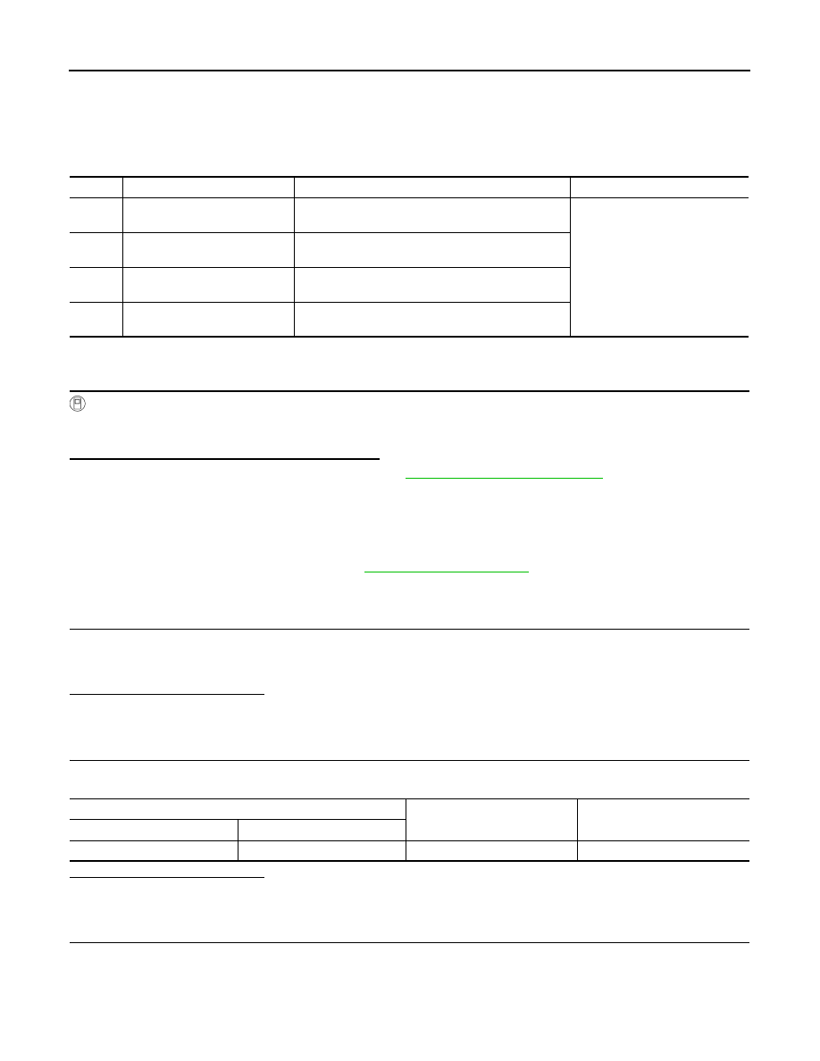
DTC
Display Item
Malfunction detected condition
Possible causes
C1121
FR LH OUT ABS SOL
When a malfunction is detected in front LH ABS OUT
valve.
• Harness or connector
• ABS actuator and electric unit
(control unit)
• Fusible link
• Battery power supply system
C1123
FR RH OUT ABS SOL
When a malfunction is detected in front RH ABS OUT
valve.
C1125
RR LH OUT ABS SOL
When a malfunction is detected in rear LH ABS OUT
valve.
C1127
RR RH OUT ABS SOL
When a malfunction is detected in rear RH ABS OUT
valve.
ABS actuator and electric unit (control unit)
—
Voltage
(Approx.)
Connector
Terminal
E33
25
Ground
Battery voltage