Nissan Versa Note. Manual - part 85
BCS
SYSTEM
BCS-77
< SYSTEM DESCRIPTION >
[WITHOUT INTELLIGENT KEY SYSTEM]
C
D
E
F
G
H
I
J
K
L
B
A
O
P
N
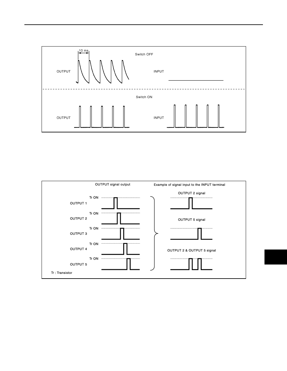
COMBINATION SWITCH READING FUNCTION
Description
• BCM reads the status of the combination switch at 10 ms intervals normally.
NOTE:
BCM reads the status of the combination switch at 60 ms intervals when BCM is controlled at low power
consumption control mode.
• BCM operates as follows and judges the status of the combination switch.
- It operates the transistor on OUTPUT side in the following order: OUTPUT 1
→ 2 → 3 → 4 → 5, and outputs
voltage waveform.
- The voltage waveform of OUTPUT corresponding to the formed circuit is input into the interface on INPUT
side if any (1 or more) switches are ON.
- It reads this change of the voltage as the status signal of the combination switch.
Operation Example
In the following operation example, the combination of the status signals of the combination switch is replaced
as follows: INPUT 1 - 5 to “1 - 5” and OUTPUT 1 - 5 to “A - E”.
Example 1: When a switch (TAIL LAMP) is turned ON
• The circuit between OUTPUT 4 and INPUT 5 is formed when the TAIL LAMP switch is turned ON.
JPMIA0609GB
JMMIA0326GB