Nissan Note E12. Manual - part 600
C1601 BATTERY POWER SUPPLY
STC-19
< DTC/CIRCUIT DIAGNOSIS >
C
D
E
F
H
I
J
K
L
M
A
B
STC
N
O
P
2. Turn ignition switch ON.
CAUTION:
Never start the engine.
3. Check voltage between EPS control unit harness connector and ground.
Is the inspection result normal?
YES
>> GO TO 4.
NO
>> GO TO 3.
3.
CHECK EPS CONTROL UNIT POWER SUPPLY CIRCUIT (2)
1. Turn ignition switch OFF.
2. Check the 10A fuse (No. 5).
3. Check the harness for open or short between EPS control unit harness connector M53 terminal 4 and the
10A fuse (No. 5).
Is the inspection result normal?
YES
>> Perform the trouble diagnosis for ignition power supply circuit. Refer to
NO
>> Repair or replace malfunctioning component.
4.
CHECK EPS CONTROL UNIT POWER SUPPLY CIRCUIT (3)
1. Turn ignition switch OFF.
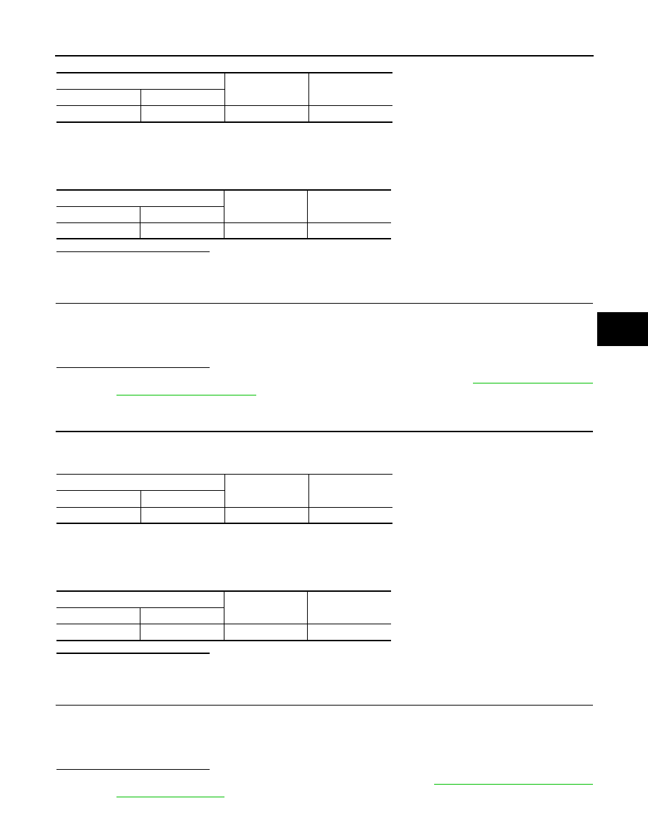
2. Check voltage between EPS control unit harness connector terminal and ground.
3. Turn ignition switch ON.
CAUTION:
Never start the engine.
4. Check voltage between EPS control unit harness connector and ground.
Is the inspection result normal?
YES
>> GO TO 6.
NO
>> GO TO 5.
5.
CHECK EPS CONTROL UNIT POWER SUPPLY CIRCUIT (4)
1. Turn ignition switch OFF.
2. Check the 60A fusible link (J).
3. Check the harness for open or short between EPS control unit harness connector E23 terminal 17 and the
60A fusible link (J).
Is the inspection result normal?
YES
>> Perform the trouble diagnosis for power supply circuit. Refer to
.
EPS control unit
—
Voltage
Connector
Terminal
M53
4
Ground
Approx. 0 V
EPS control unit
—
Voltage
Connector
Terminal
M53
4
Ground
Battery voltage
EPS control unit
—
Voltage
Connector
Terminal
E23
17
Ground
Battery voltage
EPS control unit
—
Voltage
Connector
Terminal
E23
17
Ground
Battery voltage