Nissan Note E12. Manual - part 385
COMPONENT PARTS
INL-5
< SYSTEM DESCRIPTION >
C
D
E
F
G
H
I
J
K
M
A
B
INL
N
O
P
SYSTEM DESCRIPTION
COMPONENT PARTS
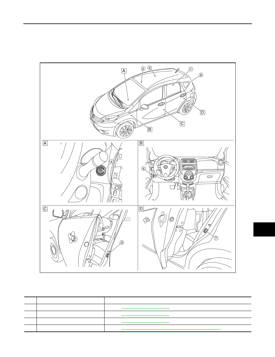
Component Parts Location
INFOID:0000000009560561
A. View right of steering column
B. Instrument panel view
C. B-pillar LH side (view with door open)
D. C-pillar LH side (view with door open)
No.
Part
Description
1.
Cargo lamp
.
2.
Interior room lamp
.
3.
Map lamp
.
4.
Push-button ignition switch
STR-4, "STARTING SYSTEM : Component Parts Location"
.
ALLIA1296ZZ