Nissan Note E12. Manual - part 30


  Index      Nissan     Nissan Note E12 - Service and Repair Manual


Search            


Content   ..  28  29  30  31   ..


Nissan Note E12. Manual - part 30


AV-112

< SYSTEM DESCRIPTION >

[NAVIGATION]

SYSTEM

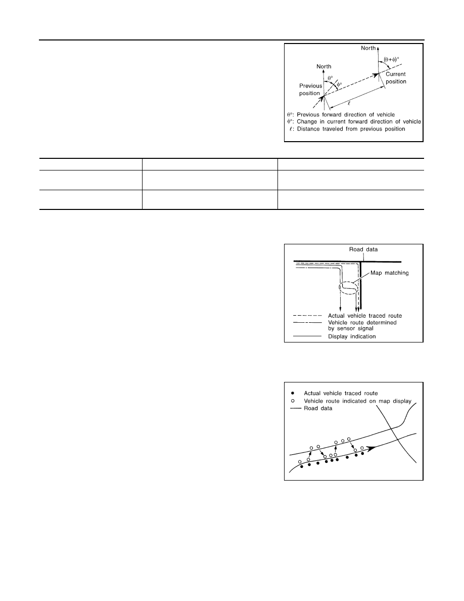
The current vehicle position will be calculated by detecting the dis-

tance the vehicle moved from the previous calculation point and its

direction.

• Travel distance

Travel distance calculations are based on the vehicle speed sen-

sor input signal. Therefore, the calculation may become incorrect

as the tires wear down. To prevent this, an automatic distance cor-

rection function has been adopted.

• Travel direction

Change in the travel direction of the vehicle is calculated by a gyro-

scope (angular velocity sensor) and a GPS antenna (GPS informa-

tion). They have both advantages and disadvantages.

More accurate traveling direction is detected because priorities are set for the signals from these two

devices according to the situation.

MAP-MATCHING

Map-matching compares a current location detected by the method

in the “Location Detection Principle” with a road map data from map

SD-card.

NOTE:

The road map data is based on data stored in the map SD-card.

The vehicle position may not be corrected under the following circumstances and after driving for a certain

time when GPS information is difficult to receive. In this case, the vehicle mark on the display must be cor-

rected manually.

• In map-matching, alternative routes to reach the destination will be

shown and prioritized, after the road on which the vehicle is cur-

rently driven has been judged and the vehicle mark has been repo-

sitioned.

Alternative routes will be shown in different order of priority, and

the incorrect road can be avoided if there is an error in distance

and/or direction.

Routes are of the same priority if two roads are running in parallel.

Therefore, the vehicle mark may appear on either of them alter-

nately, depending on maneuvering of the steering wheel and con-

figuration of the road.

SEL684V

Type

Advantage

Disadvantage

Gyroscope
(angular velocity sensor)

Can detect the vehicle's turning angle quite 
accurately.

Direction errors may accumulate when vehicle is 
driven for long distances without stopping.

GPS antenna
(GPS information)

Can detect the vehicle's travel direction 
(North/South/East/West).

Correct direction cannot be detected when vehicle 
speed is low.

SEL685V

SEL686V

AV

SYSTEM

AV-113

< SYSTEM DESCRIPTION >

[NAVIGATION]

C

D

E

F

G

H

I

J

K

L

M

B

A

O

P

• Map-matching does not function correctly when a road on which

the vehicle is driving is new and not recorded in the map SD-card,

or when road pattern stored in the map data and the actual road

pattern are different due to repair.

The map-matching function may find another road and position the

vehicle mark on it when driving on a road not present in the map.

Then, the vehicle mark may change to it when the correct road is

detected.

• Effective range for comparing the vehicle position and travel direc-

tion calculated by the distance and direction with the road data

read from the map SD-card is limited. Therefore, correction by

map-matching is not possible when there is an excessive gap

between current vehicle position and the position on the map.

GPS (Global Positioning System)

GPS (Global Positioning System) is developed for and is controlled

by the US Department of Defense. The system utilizes GPS satel-

lites (NAVSTAR), transmitting out radio waves while flying on an orbit

around the earth at an altitude of approximately 21,000 km (13,049

mile).

The receiver calculates the travel position in three dimensions (lati-

tude/longitude/altitude) according to the time lag of the radio waves

that four or more GPS satellites transmit (three-dimensional position-

ing). The GPS receiver calculates the travel position in two dimen-

sions (latitude/longitude) with the previous altitude data if the GPS

receiver receives only three radio waves (two-dimensional position-

ing). GPS position correction is not performed while stopping the

vehicle.

Accuracy of the GPS will deteriorate under the following conditions:

• In two-dimensional positioning, GPS accuracy will deteriorate when altitude of the vehicle position changes.

• The position of GPS satellite affects GPS detection precision. The position detection may not be precisely

performed.

• The position detection is not performed if GPS receiver does not receive radio waves from GPS satellites.

(Inside a tunnel, parking in a building, under an elevated highway etc.) GPS receiver may not receive radio

waves from GPS satellites if any object is placed on the GPS antenna.

NOTE:

• The detection result has an error of approximately 10 m (32.81 ft) even with a high-precision three dimen-

sional positioning.

• There may be cases when the accuracy is lowered and radio waves are stopped intentionally because the

GPS satellite signal is controlled by the US trace control center.

REAR VIEW MONITOR

Camera Image Operation Principle

• The AV control unit supplies power to the rear view camera when receiving a reverse signal.

• The rear view camera transmits camera images to the AV control unit.

• The AV control unit combines a warning message and fixed guide lines with an image received from the rear

view camera.

USB INTERFACE

• iPod

®

 or music files in USB memory can be played. 

• Sound signals are transmitted from USB interface to the AV control unit and output to each speaker.
• iPod

®

 is recharged when connected to USB interface.

AUX IN JACK

• Sound can be output from an external device by connecting a device to the AUX in jack.

• AUX sound signals are transmitted to each speaker via AV control unit.

SPEED SENSITIVE VOLUME SYSTEM

• Volume level of this system goes up and down automatically in proportion to the vehicle speed.

• The control level can be selected by the customer.

SKIA0613E

SEL526V

AV-114

< SYSTEM DESCRIPTION >

[NAVIGATION]

SYSTEM

HANDS-FREE PHONE SYSTEM

• Bluetooth

®

 control is built into AV control unit.

• The connection between cellular phone and AV control unit is performed with Bluetooth

®

 communication.

• The voice guidance signal is input from the AV control unit and output to the front speakers when operating

the cellular phone.

When A Call Is Originated

• Spoken voice sound output from the microphone (microphone signal) is input to AV control unit. 
• AV control unit outputs to cellular phone with Bluetooth

®

 communication as a TEL voice signal. 

• Voice sound is then heard at the other party.

When Receiving A Call

• Voice sound is input to own cellular phone from the other party. 
• TEL voice signal is input to AV control unit by establishing Bluetooth

®

 communication from cellular phone,

and the signal is output to front speakers.

AV

DIAGNOSIS SYSTEM (AV CONTROL UNIT)

AV-115

< SYSTEM DESCRIPTION >

[NAVIGATION]

C

D

E

F

G

H

I

J

K

L

M

B

A

O

P

DIAGNOSIS SYSTEM (AV CONTROL UNIT)

Description

INFOID:0000000009460259

The AV control unit on board diagnosis performs the functions listed in the table below:

Perform CONSULT diagnosis if the AV control unit on board diagnosis does not start or the screen does not

display anything.

On Board Diagnosis Function

INFOID:0000000009460260

METHOD OF STARTING

1. Turn the ignition ON.

2. Turn the audio system OFF.

Mode

Item

Content

Version

Version data of the AV control unit is dis-
played.

User Configuration

Touch Display Calibration

Allows correction of the position detec-
tion accuracy of the touch panel.

Radio

FM monitor

Monitors the dynamic values of the cur-
rent tuner

AM monitor

XM monitor

Version data is displayed.

XM functions

• Clear XM Chipset NVM
• Reset All XM Settings 
• Clear IGS
• XM CBM Debug Mode
• External Diag Mode

Current status is displayed.

System State

Running System Status

• SD card slot Access
• Power Supply 
• Speed Signal
• Direction Signal
• Illumination Signal
• GPS Antenna 
• GPS Tracking 
• Satellites Visible 
• Satellites Tracked 
• Microphone Current 
• Steering wheel key
• Radio Antenna 
• USB Device 
• iPod

®

 firmware version 

The current system status is displayed.

Speaker Test 4kHz

This activates a sequence of test tone 
outputs to the audio circuits one after the 
other for 1 second. 

Speaker Test 100Hz

Display-Test

This provides a test sequence where 
test displays (plain colored display: e.g. 
white, black, red, blue, green) are shown 
one after the other. 
The respective color is shown for an in-
dicated period of time (parameter). After 
the display test, the design of the display 
previously available is stored. While the 
screen shows a plain colored display, a 
pixel malfunction may be detected.

Self Test

• SD Card Access 
• BT Module Access
• Radio Antenna
• GPS Antenna
• XM Antenna

A system self test is executed and the 
results are stored into the error memory.


Content   ..  28  29  30  31   ..