Nissan Rogue. Manual - part 986
PWC-26
< BASIC INSPECTION >
DIAGNOSIS AND REPAIR WORKFLOW
BASIC INSPECTION
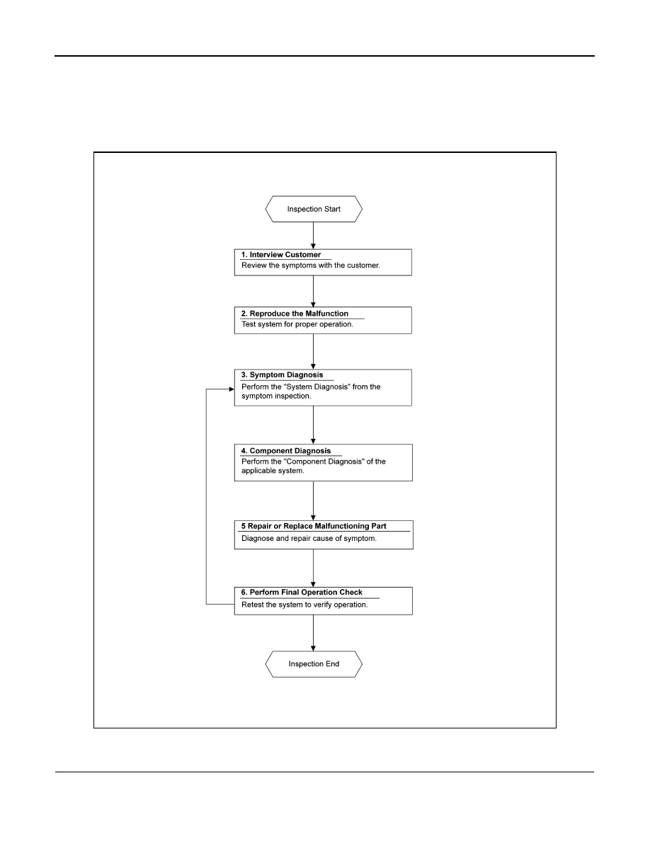
DIAGNOSIS AND REPAIR WORKFLOW
Work Flow
INFOID:0000000011278683
OVERALL SEQUENCE
DETAILED FLOW
1.
INTERVIEW CUSTOMER
Interview the customer to obtain as much information as possible about the conditions and environment under
which the malfunction occurred.
ALKIA1982GB