Nissan Rogue. Manual - part 906


  Index      Nissan     Nissan Rogue (2015 year) - Service and Repair Manual


Search            


Content   ..  904  905  906  907   ..


Nissan Rogue. Manual - part 906


CHASSIS MAINTENANCE

MA-39

< PERIODIC MAINTENANCE >

C

D

E

F

G

H

I

J

K

L

M

B

MA

N

O

A

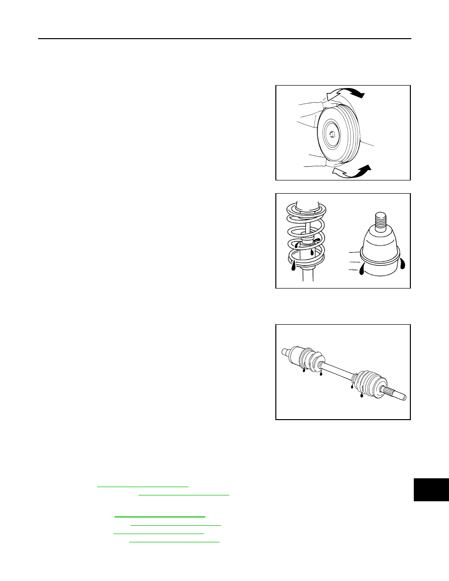
Check ball joint, dust cover and other component parts for looseness, wear, damage and grease leakage.

AXLE AND SUSPENSION PARTS
AXLE AND SUSPENSION PARTS : Inspection

INFOID:0000000011277809

Check front and rear axle and suspension parts for excessive play,

cracks, wear or other damage.

• Shake each wheel to check for excessive play.

• Check wheel bearings for smooth operation.

• Check axle and suspension nuts and bolts for looseness.

• Check strut (shock absorber) for oil leakage or other damage.

• Check suspension ball joint for grease leakage and ball joint dust

cover for cracks or other damage.

DRIVE SHAFT
DRIVE SHAFT : Inspection

INFOID:0000000011277810

• Check boot and drive shaft for cracks, wear, damage and grease

leakage.

LOCKS, HINGES AND HOOD LATCH
LOCKS, HINGES AND HOOD LATCH : Lubricating

INFOID:0000000011277811

WITH INTELLIGENT KEY SYSTEM

For hood and hood lock illustration.

• Hood: Refer to 

DLK-240, "Exploded View"

• Hood lock control: Refer to 

DLK-240, "Exploded View"

.

For front door and front door lock illustration.

• Front door: Refer to 

DLK-247, "Exploded View"

.

• Front door lock: Refer to 

DLK-263, "Exploded View"

.

• Rear door: Refer to 

DLK-251, "Exploded View"

.

• Rear door lock: Refer to 

DLK-267, "Exploded View"

.

For back door and back door lock illustration.

SMA525A

JPPIA0011ZZ

SFA108A

MA-40

< PERIODIC MAINTENANCE >

CHASSIS MAINTENANCE

• Back door: Refer to 

DLK-255, "Exploded View"

.

• Back door lock: Refer to 

DLK-270, "Exploded View"

.

WITHOUT INTELLIGENT KEY SYSTEM

For hood and hood lock illustration.

• Hood: Refer to 

DLK-361, "Exploded View"

• Hood lock control: Refer to 

DLK-381, "Exploded View"

.

For front door and front door lock illustration.

• Front door: Refer to 

DLK-368, "Exploded View"

.

• Front door lock: Refer to 

DLK-388, "Exploded View"

.

• Rear door: Refer to 

DLK-372, "Exploded View"

.

• Rear door lock: Refer to 

DLK-388, "Exploded View"

.

For back door and back door lock illustration.

• Back door: Refer to 

DLK-376, "Exploded View"

.

• Back door lock: Refer to 

DLK-391, "Exploded View"

.

SEAT BELT, BUCKLES, RETRACTORS, ANCHORS AND ADJUSTERS
SEAT BELT, BUCKLES, RETRACTORS, ANCHORS AND ADJUSTERS : Inspection

INFOID:0000000011277812

For front seat belt illustration. Refer to 

SB-8, "Exploded View"

.

For rear seat belt illustration. Refer to 

SB-12, "Exploded View"

.

CAUTION:

• After any collision, inspect all seat belt assemblies, including retractors and other attached hard-

wares (I.e. anchor bolt, guide rail set). Nissan recommends to replace all seat belt assemblies in use

during a collision, unless not damaged and properly operating after minor collision.

Also inspect seat belt assemblies not in use during a collision, and replace if damaged or improperly

operating.

Seat belt pre-tensioner should be replaced even if the seat belts are not in use during a frontal colli-

sion where the driver and passenger air bags are deployed.

• If any component of seat belt assembly is questionable, do not repair.

Replace as seat belt assembly.

• If webbing is cut, frayed, or damaged, replace belt assembly.

• Never oil tongue and buckle.

• Use a genuine NISSAN seat belt assembly.

For details, refer to 

SB-5, "Inspection"

 in SB section.

• Check anchors for loose mounting

• Check belts for damage

• Check retractor for smooth operation

• Check function of buckles and tongues when buckled and released

MIR-1

DRIVER CONTROLS

C

D

E

F

G

H

I

J

K

M

SECTION 

MIR

A

B

MIR

N

O

P

CONTENTS

MIRRORS

PRECAUTION ...............................................

2

PRECAUTIONS ...................................................

2

Precaution for Supplemental Restraint System 
(SRS) "AIR BAG" and "SEAT BELT PRE-TEN-
SIONER" .................................................................
..

2

Precaution for Work  ..................................................

2

PREPARATION ............................................

3

PREPARATION ...................................................

3

Special Service Tool  .................................................

3

Commercial Service Tools .......................................

3

WIRING DIAGRAM .......................................

4

INSIDE MIRROR  .................................................

4

Wiring Diagram - With Homelink Universal Trans-
ceiver .......................................................................
..

4

Wiring Diagram - Without Homelink Universal 
Transceiver .............................................................
..

7

DOOR MIRROR ..................................................

10

Wiring Diagram  .......................................................

10

DTC/CIRCUIT DIAGNOSIS  .........................

13

DOOR MIRROR REMOTE CONTROL 
SWITCH ..............................................................

13

Component Inspection  ............................................

13

SYMPTOM DIAGNOSIS  ..............................

14

SQUEAK AND RATTLE TROUBLE DIAG-
NOSES ..............................................................

14

Work Flow ................................................................

14

Generic Squeak and Rattle Troubleshooting ...........

15

Diagnostic Worksheet ..............................................

18

REMOVAL AND INSTALLATION ...............

20

INSIDE MIRROR  ...............................................

20

Exploded View .........................................................

20

Removal and Installation  .........................................

20

DOOR MIRROR  ................................................

22

Exploded View .........................................................

22

Removal and Installation  .........................................

22

DOOR MIRROR GLASS  ...................................

24

Removal and Installation  .........................................

24

DOOR MIRROR ACTUATOR  ...........................

25

Removal and Installation  .........................................

25

DOOR MIRROR REAR FINISHER  ...................

26

Removal and Installation  .........................................

26

SIDE CAMERA FINISHER ................................

27

Removal and Installation  .........................................

27

DOOR MIRROR REMOTE CONTROL 
SWITCH .............................................................

28

Removal and Installation  .........................................

28

MIR-2

< PRECAUTION >

PRECAUTIONS

PRECAUTION

PRECAUTIONS

Precaution for Supplemental Restraint System (SRS) "AIR BAG" and "SEAT BELT 
PRE-TENSIONER"

INFOID:0000000011280681

The Supplemental Restraint System such as “AIR BAG” and “SEAT BELT PRE-TENSIONER”, used along

with a front seat belt, helps to reduce the risk or severity of injury to the driver and front passenger for certain

types of collision. Information necessary to service the system safely is included in the SR and SB section of

this Service Manual.

WARNING:

• To avoid rendering the SRS inoperative, which could increase the risk of personal injury or death in

the event of a collision which would result in air bag inflation, all maintenance must be performed by

an authorized NISSAN/INFINITI dealer.

• Improper maintenance, including incorrect removal and installation of the SRS, can lead to personal

injury caused by unintentional activation of the system. For removal of Spiral Cable and Air Bag

Module, see the SR section.

• Do not use electrical test equipment on any circuit related to the SRS unless instructed to in this

Service Manual. SRS wiring harnesses can be identified by yellow and/or orange harnesses or har-

ness connectors.

PRECAUTIONS WHEN USING POWER TOOLS (AIR OR ELECTRIC) AND HAMMERS

WARNING:

• When working near the Airbag Diagnosis Sensor Unit or other Airbag System sensors with the Igni-

tion ON or engine running, DO NOT use air or electric power tools or strike near the sensor(s) with a

hammer. Heavy vibration could activate the sensor(s) and deploy the air bag(s), possibly causing

serious injury.

• When using air or electric power tools or hammers, always switch the Ignition OFF, disconnect the

battery and wait at least three minutes before performing any service.

Precaution for Work

INFOID:0000000011280682

• When removing or disassembling each component, be careful not to damage or deform it. If a component

may be subject to interference, be sure to protect it with a shop cloth.

• When removing (disengaging) components with a screwdriver or similar tool, be sure to wrap the component

with a shop cloth or vinyl tape to protect it.

• Protect the removed parts with a shop cloth and prevent them from being dropped.

• Replace a deformed or damaged clip.

• If a part is specified as a non-reusable part, always replace it with a new one.

• Be sure to tighten bolts and nuts securely to the specified torque.

• After installation is complete, be sure to check that each part works properly.

• Follow the steps below to clean components:

- Water soluble dirt:

• Dip a soft cloth into lukewarm water, wring the water out of the cloth and wipe the dirty area.

• Then rub with a soft, dry cloth.

- Oily dirt:

• Dip a soft cloth into lukewarm water with mild detergent (concentration: within 2 to 3%) and wipe the dirty

area.

• Then dip a cloth into fresh water, wring the water out of the cloth and wipe the detergent off.

• Then rub with a soft, dry cloth.

- Do not use organic solvent such as thinner, benzene, alcohol or gasoline.

- For genuine leather seats, use a genuine leather seat cleaner.


Content   ..  904  905  906  907   ..