Nissan Rogue. Manual - part 718


  Index      Nissan     Nissan Rogue (2015 year) - Service and Repair Manual


Search            


Content   ..  716  717  718  719   ..


Nissan Rogue. Manual - part 718


PRECAUTIONS

GI-23

< PRECAUTION >

C

D

E

F

G

H

I

J

K

L

M

B

GI

N

O

P

PRECAUTION

PRECAUTIONS

Description

INFOID:0000000011278251

Observe the following precautions to ensure safe and proper servicing. These precautions are not

described in each individual section.

Precaution for Supplemental Restraint System (SRS) "AIR BAG" and "SEAT BELT 
PRE-TENSIONER"

INFOID:0000000011278252

The Supplemental Restraint System such as “AIR BAG” and “SEAT BELT PRE-TENSIONER”, used along

with a front seat belt, helps to reduce the risk or severity of injury to the driver and front passenger for certain

types of collision. Information necessary to service the system safely is included in the SR and SB section of

this Service Manual.

WARNING:

• To avoid rendering the SRS inoperative, which could increase the risk of personal injury or death in

the event of a collision which would result in air bag inflation, all maintenance must be performed by

an authorized NISSAN/INFINITI dealer.

• Improper maintenance, including incorrect removal and installation of the SRS, can lead to personal

injury caused by unintentional activation of the system. For removal of Spiral Cable and Air Bag

Module, see the SR section.

• Do not use electrical test equipment on any circuit related to the SRS unless instructed to in this

Service Manual. SRS wiring harnesses can be identified by yellow and/or orange harnesses or har-

ness connectors.

PRECAUTIONS WHEN USING POWER TOOLS (AIR OR ELECTRIC) AND HAMMERS

WARNING:

• When working near the Airbag Diagnosis Sensor Unit or other Airbag System sensors with the Igni-

tion ON or engine running, DO NOT use air or electric power tools or strike near the sensor(s) with a

hammer. Heavy vibration could activate the sensor(s) and deploy the air bag(s), possibly causing

serious injury.

• When using air or electric power tools or hammers, always switch the Ignition OFF, disconnect the

battery and wait at least three minutes before performing any service.

Procedures without Cowl Top Cover

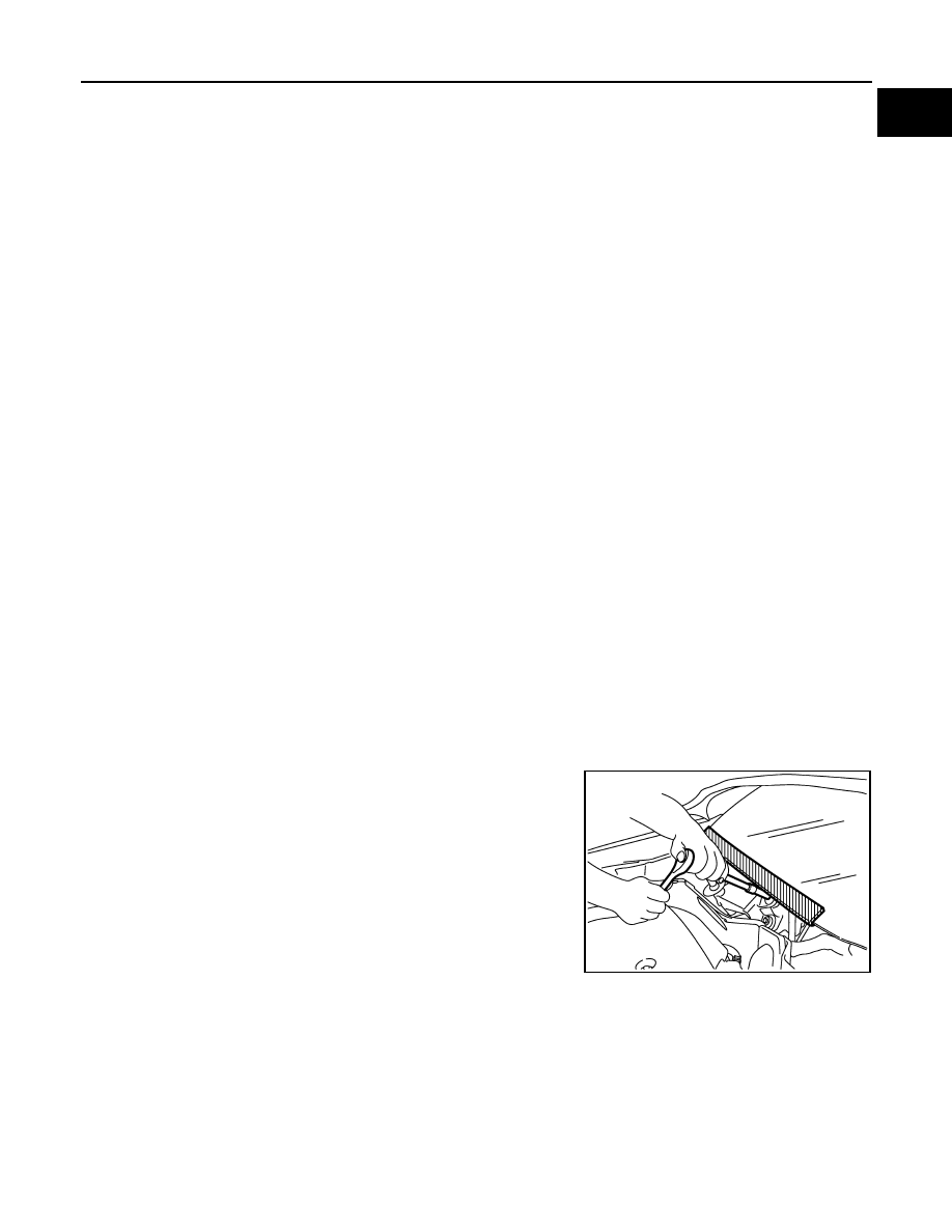
INFOID:0000000011278253

When performing the procedure after removing cowl top cover, cover

the lower end of windshield with urethane, etc.

Cautions in Removing Battery Terminal and AV Control Unit (Models with AV Control 
Unit)

INFOID:0000000011278254

CAUTION:

Remove battery terminal and AV control unit after a lapse of 30 seconds or more after turning the igni-

tion switch OFF.

NOTE:

After the ignition switch is turned OFF, the AV control unit continues operating for approximately 30 seconds.

Therefore, data corruption may occur if battery voltage is cut off within 30 seconds. 

PIIB3706J

GI-24

< PRECAUTION >

PRECAUTIONS

General Precautions

INFOID:0000000011278255

• Do not operate the engine for an extended period of time without

proper exhaust ventilation.

Keep the work area well ventilated and free of any inflammable

materials. Special care should be taken when handling any inflam-

mable or poisonous materials, such as gasoline, refrigerant gas,

etc. When working in a pit or other enclosed area, be sure to prop-

erly ventilate the area before working with hazardous materials.

Do not smoke while working on the vehicle.

• Before jacking up the vehicle, apply wheel chocks or other tire

blocks to the wheels to prevent the vehicle from moving. After jack-

ing up the vehicle, support the vehicle weight with safety stands at

the points designated for proper lifting before working on the vehi-

cle.

These operations should be done on a level surface.

• When removing a heavy component such as the engine or tran-

saxle/transmission, be careful not to lose your balance and drop

them. Also, do not allow them to strike adjacent parts, especially

the brake tubes and master cylinder.

• Before starting repairs which do not require battery power:

Turn off ignition switch.

Disconnect the negative battery terminal.

• If the battery terminals are disconnected, recorded memory of

radio and each control unit is erased.

• To prevent serious burns:

Avoid contact with hot metal parts.

Do not remove the radiator cap when the engine is hot.

• Dispose of drained oil or the solvent used for cleaning parts in an

appropriate manner.

• Do not attempt to top off the fuel tank after the fuel pump nozzle

shuts off automatically.

Continued refueling may cause fuel overflow, resulting in fuel spray

and possibly a fire.

• Clean all disassembled parts in the designated liquid or solvent

prior to inspection or assembly.

• Replace oil seals, gaskets, packings, O-rings, locking washers,

cotter pins, self-locking nuts, etc. with new ones.

• Replace inner and outer races of tapered roller bearings and needle bearings as a set.

• Arrange the disassembled parts in accordance with their assembled locations and sequence.

• Do not touch the terminals of electrical components which use microcomputers (such as ECM).

Static electricity may damage internal electronic components.

• After disconnecting vacuum or air hoses, attach a tag to indicate the proper connection.

• Use only the fluids and lubricants specified in this manual.

• Use approved bonding agent, sealants or their equivalents when required.

SGI285

SGI231

SEF289H

SGI233

PRECAUTIONS

GI-25

< PRECAUTION >

C

D

E

F

G

H

I

J

K

L

M

B

GI

N

O

P

• Use hand tools, power tools (disassembly only) and recommended

special tools where specified for safe and efficient service repairs.

• When repairing the fuel, oil, water, vacuum or exhaust systems,

check all affected lines for leaks.

• Before servicing the vehicle:

Protect fenders, upholstery and carpeting with appropriate covers.

Take caution that keys, buckles or buttons do not scratch paint.

WARNING:

To prevent ECM from storing the diagnostic trouble codes, do not carelessly disconnect the harness

connectors which are related to the engine control system and TCM (transmission control module)

system. The connectors should be disconnected only when working according to the WORK FLOW of

TROUBLE DIAGNOSES in EC and TM sections.

Three Way Catalyst

INFOID:0000000011278256

If a large amount of unburned fuel flows into the catalyst, the catalyst temperature will be excessively high. To

prevent this, follow the instructions.

• Use unleaded gasoline only. Leaded gasoline will seriously damage the three way catalyst.

• When checking for ignition spark or measuring engine compression, make tests quickly and only when nec-

essary.

• Do not run engine when the fuel tank level is low, otherwise the engine may misfire, causing damage to the

catalyst.

Do not place the vehicle on flammable material. Keep flammable material off the exhaust pipe and the three

way catalyst.

Fuel (Regular Unleaded Gasoline Recommended)

INFOID:0000000011278257

Use unleaded regular gasoline with an octane rating of at least 87 AKI (Anti-Knock Index) number (Research

octane number 91). E-85 fuel (85% fuel ethanol, 15% unleaded gasoline) may only be used in vehicles specif-

ically designed for E-85 fuel (i.e. Flexible Fuel Vehicle - FFV models).

CAUTION:

Do not use leaded gasoline. Using leaded gasoline will damage the three way catalyst. Do not use E-85

fuel (85% fuel ethanol, 15% unleaded gasoline) unless the vehicle is specifically designed for E-85 fuel

(i.e. Flexible Fuel Vehicle - FFV models). Using a fuel other than that specified could adversely affect

the emission control devices and systems, and could also affect the warranty coverage validity.

JPAIA0335ZZ

SGI234

GI-26

< PRECAUTION >

PRECAUTIONS

Multiport Fuel Injection System or Engine Control System

INFOID:0000000011278258

• Before connecting or disconnecting any harness connector for the

multiport fuel injection system or ECM:

Turn ignition switch to “OFF” position.

Disconnect negative battery terminal.

Otherwise, there may be damage to ECM.

• Before disconnecting pressurized fuel line from fuel pump to injec-

tors, be sure to release fuel pressure.

• Be careful not to jar components such as ECM and mass air flow

sensor.

Hoses

INFOID:0000000011278259

HOSE REMOVAL AND INSTALLATION

• To prevent damage to rubber hose, do not pry off rubber hose with

tapered tool or screwdriver.

• To reinstall the rubber hose securely, make sure that hose insertion

length and orientation is correct. (If tube is equipped with hose

stopper, insert rubber hose into tube until it butts up against hose

stopper.)

HOSE CLAMPING

• If old rubber hose is re-used, install hose clamp in its original posi-

tion (at the indentation where the old clamp was). If there is a trace

of tube bulging left on the old rubber hose, align rubber hose at

that position. 

• Discard old clamps; replace with new ones.

SGI787

SMA019D

SMA020D

SMA021D


Content   ..  716  717  718  719   ..