Nissan Rogue. Manual - part 707


  Index      Nissan     Nissan Rogue (2015 year) - Service and Repair Manual


Search            


Content   ..  705  706  707  708   ..


Nissan Rogue. Manual - part 707


FRONT STABILIZER

FSU-17

< REMOVAL AND INSTALLATION >

C

D

F

G

H

I

J

K

L

M

A

B

FSU

N

O

P

12. Gradually lower the jack and the rear of the front suspension

member in order to remove stabilizer clamp bolts.

13. Remove stabilizer clamp bolts (

), and then remove stabilizer

clamp and stabilizer bushing from front suspension member.

14. Remove stabilizer bar.

INSPECTION AFTER REMOVAL

Check the stabilizer bar, the stabilizer connecting rod, the stabilizer bushing and the stabilizer clamp for defor-

mation, cracks or damage. Replace components if necessary.

INSTALLATION

Installation is in the reverse order of removal.

CAUTION:

• With the steering linkage disconnected, the spiral cable may snap by turning the steering wheel

beyond the limited number of turns. Secure the steering wheel during installation of the stabilizer

bar.

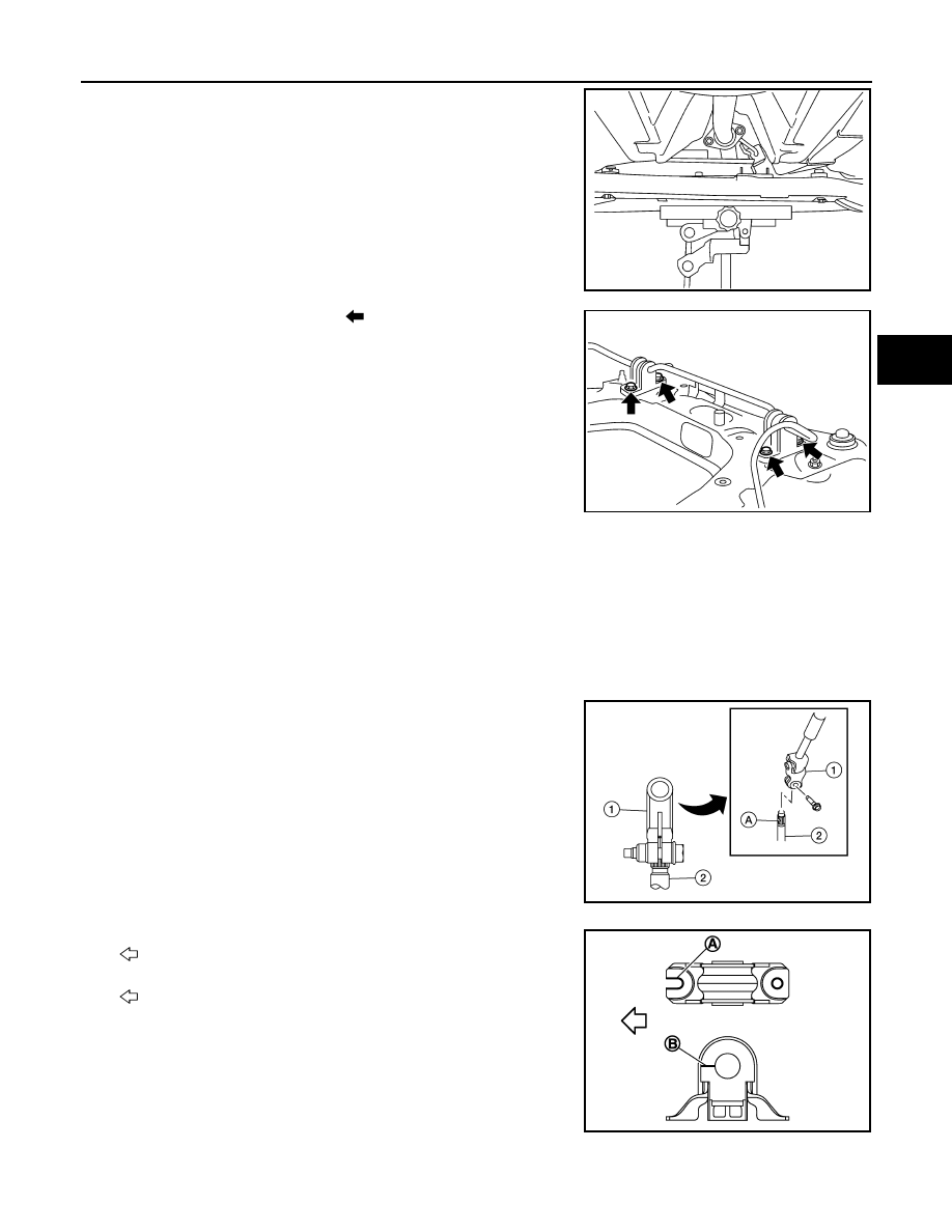
• When connecting the steering column (1) to the steering gear

pinion shaft (2), be sure that the gap (A) lines up with the joint

retaining bolt hole. 

• Make sure the bolt is in the correct direction, as shown, and is

securely seated in the groove.

1. Install stabilizer clamp so that notch (A) is facing front of vehicle

(

).

2. Install stabilizer bushing so that slit (B) is facing front of vehicle

(

).

WEIA0181E

WEIA0182E

AWGIA0320ZZ

JPEIA0058ZZ

FSU-18

< REMOVAL AND INSTALLATION >

FRONT STABILIZER

3. Install the stabilizer clamp bolts in the order of 1 to 5 as shown.

4. To connect the stabilizer connecting rod (1), tighten the nut while

holding the hexagonal part (A) on the stabilizer connecting rod.

5. Perform the final tightening of the nuts and bolts under unladen conditions with the tires on level ground.

INSPECTION AFTER INSTALLATION

1. Check the wheel alignment. Refer to 

FSU-7, "Inspection"

.

2. Perform the steering angle sensor neutral position adjustment. Refer to 

BRC-68, "Work Procedure"

.

Manual tightening

: 1

Temporary tightening

: 2 

→ 3

Final tightening (Specified torque) 

: 4 

→ 5

Specified torque (USA Pro-
duction)

: 33 N·m (3.4 kg-m, 24 ft-lb)

Specified torque (Korea 
Production)

: 24 N·m (2.4 kg-m, 18 ft-lb)

: Front

JPEIA0245GB

JPEIA0252ZZ

STEERING KNUCKLE

FSU-19

< REMOVAL AND INSTALLATION >

C

D

F

G

H

I

J

K

L

M

A

B

FSU

N

O

P

STEERING KNUCKLE

Exploded View

INFOID:0000000011277058

Removal and Installation

INFOID:0000000011277059

REMOVAL

1. Remove the wheel and tire using power tool. Refer to 

WT-67, "Removal and Installation"

.

2. Remove the (1) bolt and separate the front wheel sensor from

the steering knuckle. Refer to 

BRC-130, "FRONT WHEEL SEN-

SOR : Exploded View"

.

CAUTION:

• Failure to separate the front wheel sensor from the steer-

ing knuckle may result in damage to the front wheel sen-

sor.

• Pull out the front wheel sensor, being careful to turn it as

little as possible. Do not pull on wheel sensor harness.

3. Remove brake caliper torque member bolts, leaving the brake hose attached. Position brake caliper aside

with wire. Refer to 

BR-37, "BRAKE CALIPER ASSEMBLY (1 PISTON TYPE) : Exploded View"

 (1 PISTON

TYPE), or 

BR-42, "BRAKE CALIPER ASSEMBLY (2 PISTON TYPE) : Exploded View"

 (2 PISTON TYPE).

CAUTION:

Do not depress brake pedal while brake caliper is removed.

1.

Disc brake rotor

2.

Nut retainer

3.

Cotter pin

4.

Wheel stud

5.

Steering knuckle

6.

Splash guard

7.

Wheel hub and bearing

A. Wheel hub lock nut

AWEIA0373ZZ

ALDIA0526ZZ

FSU-20

< REMOVAL AND INSTALLATION >

STEERING KNUCKLE

4. Put alignment marks (A) on the disc brake rotor and on the

wheel hub and bearing. Remove the disc brake rotor.

CAUTION:

Do not drop the disc brake rotor.

5. Remove the cotter pin from the drive shaft.
6. Remove the nut retainer from the wheel hub lock nut.
7. Loosen the wheel hub lock nut using power tool.
8. Using a piece of wood and a suitable tool, tap on the lock nut to

disengage the drive shaft from the wheel hub and bearing. 

CAUTION:

• Do not place the drive shaft joint at an extreme angle. Be

careful not to over extend the slide joint.

• Do not allow the drive shaft to hang without support.

NOTE:

Use a suitable puller if drive shaft cannot be separated from the

wheel hub and bearing.

9. Remove the wheel hub lock nut. Refer to 

FAX-9, "Exploded View"

 (FWD) or to 

FAX-47, "Exploded View"

(AWD).

10. Remove the nut and separate the stabilizer connecting rod from the strut bracket. Refer to 

FSU-16,

"Exploded View"

.

11. Remove the lower nut and bolt from the steering knuckle. Separate the transverse link from the steering

knuckle. Refer to 

FSU-19, "Exploded View"

.

12. Separate drive shaft from wheel hub and bearing.
13. Remove the bolts and the wheel hub and bearing and splash guard from the steering knuckle.
14. Remove the upper nut and bolt from the steering knuckle.
15. Remove the nut and separate the outer socket from the steering knuckle. Refer to 

ST-14, "Exploded

View"

.

JPDIG0066ZZ

JPDIG0070ZZ


Content   ..  705  706  707  708   ..