Nissan Rogue. Manual - part 441
EC-32
< SYSTEM DESCRIPTION >
[QR25DE]
SYSTEM
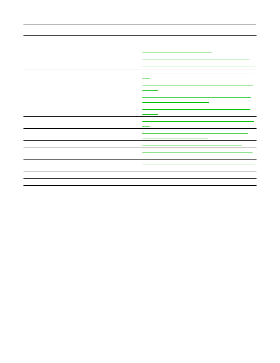
ECM controls the engine by various functions.
Function
Reference
Multiport fuel injection system
EC-37, "MULTIPORT FUEL INJECTION SYSTEM : System De-
scription (with automatic air conditioner)"
Electric ignition system
EC-41, "ELECTRIC IGNITION SYSTEM : System Description"
Intake valve timing control
EC-42, "INTAKE VALVE TIMING CONTROL : System Description"
Exhaust valve timing control
EC-45, "EXHAUST VALVE TIMING CONTROL : System Descrip-
tion"
Intake manifold runner control
EC-46, "INTAKE MANIFOLD RUNNER CONTROL : System De-
scription"
Engine protection control
EC-46, "ENGINE PROTECTION CONTROL AT LOW ENGINE
OIL PRESSURE : System Description"
Fuel filler cap warning system
EC-50, "FUEL FILLER CAP WARNING SYSTEM : System De-
scription"
Air conditioning cut control
EC-47, "AIR CONDITIONING CUT CONTROL : System Descrip-
tion"
Power generation voltage variable control
EC-47, "POWER GENERATION VOLTAGE VARIABLE CON-
TROL SYSTEM : System Description"
Cooling fan control
EC-48, "COOLING FAN CONTROL : System Description"
Evaporative emission system
EC-55, "EVAPORATIVE EMISSION SYSTEM : System Descrip-
tion"
Automatic speed control device (ASCD)
EC-49, "AUTOMATIC SPEED CONTROL DEVICE (ASCD) : Sys-
tem Description"
CAN communication
EC-55, "CAN COMMUNICATION : System Description"
Sport mode