Nissan Rogue. Manual - part 289


  Index      Nissan     Nissan Rogue (2015 year) - Service and Repair Manual


Search            


Content   ..  287  288  289  290   ..


Nissan Rogue. Manual - part 289


FILAMENT

DEF-41

< REMOVAL AND INSTALLATION >

C

D

E

F

G

H

I

J

K

M

A

B

DEF

N

O

P

REMOVAL AND INSTALLATION

FILAMENT

Inspection and Repair

INFOID:0000000011277756
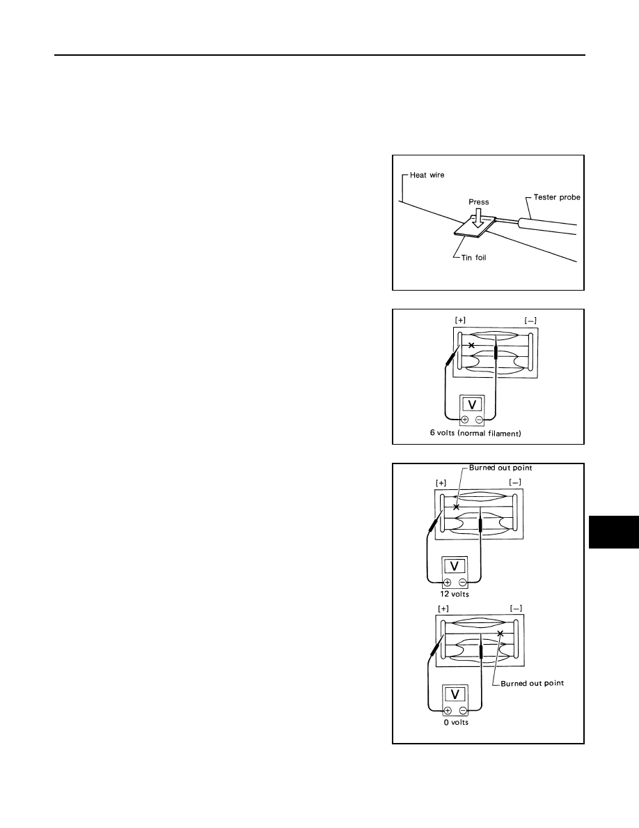
INSPECTION

1. When measuring voltage, wrap tin foil around the top of the neg-

ative probe. Then press the foil against the wire with your finger.

2. Attach probe circuit tester (in Volt range) to middle portion of

each filament.

3. If a filament is burned out, circuit tester registers 0 or battery

voltage.

4. To locate burned out point, move probe to left and right along fil-

ament. Test needle will swing abruptly when probe passes the

point.

REPAIR

REPAIR EQUIPMENT

• Conductive silver composition (Dupont No. 4817 or equivalent)

SEL122R

SEL263

SEL265

DEF-42

< REMOVAL AND INSTALLATION >

FILAMENT

• Ruler 30 cm (11.8 in) long

• Drawing pen

• Heat gun

• Alcohol

• Cloth

REPAIRING PROCEDURE

1. Wipe broken heat wire and its surrounding area clean with a

cloth dampened in alcohol.

2. Apply a small amount of conductive silver composition to tip of

drawing pen.

Shake silver composition container before use.

3. Place ruler on glass along broken line. Deposit conductive silver

composition on break with drawing pen. Slightly overlap existing

heat wire on both sides [preferably 5 mm (0.20 in)] of the break.

4. After repair has been completed, check repaired wire for conti-

nuity. This check should be conducted 10 minutes after silver

composition is deposited.

Do not touch repaired area while test is being conducted.

5. Apply a constant stream of hot air directly to the repaired area

for approximately 20 minutes with a heat gun. A minimum dis-

tance of 3 cm (1.2 in) should be kept between repaired area and

hot air outlet.

If a heat gun is not available, let the repaired area dry for 24

hours.

PIIA0215E

SEL012D

SEL013D

CONDENSER

DEF-43

< REMOVAL AND INSTALLATION >

C

D

E

F

G

H

I

J

K

M

A

B

DEF

N

O

P

CONDENSER

Removal and Installation

INFOID:0000000011277757

REMOVAL

1. Remove luggage side upper finisher (LH/RH). Refer to 

INT-36, "LUGGAGE SIDE UPPER FINISHER :

Removal and Installation"

.

2. Remove headlining clips (A) using suitable tool (B) and partially

lower headlining (rear).

3. Disconnect the harness connectors from the condenser.
4. Remove the bolt (A) and the condenser (1).

INSTALLATION

Installation is in the reverse order of removal.

ALLIA1604ZZ

ALLIA1370ZZ

DLK-1

BODY EXTERIOR, DOORS, ROOF & VEHICLE SECURITY

C

D

E

F

G

H

I

J

L

M

SECTION 

DLK

A

B

DLK

N

O

P

CONTENTS

DOOR & LOCK

WITH INTELLIGENT KEY SYSTEM

PRECAUTION ..............................................

11

PRECAUTIONS ..................................................

11

Precaution for Supplemental Restraint System 
(SRS) "AIR BAG" and "SEAT BELT PRE-TEN-
SIONER" .................................................................

11

Precaution for Servicing Doors and Locks  ..............

11

PREPARATION ...........................................

12

PREPARATION ..................................................

12

Special Service Tool  ...............................................

12

Commercial Service Tool  ........................................

13

SYSTEM DESCRIPTION  .............................

14

COMPONENT PARTS  .......................................

14

POWER DOOR LOCK SYSTEM  ...............................

14

POWER DOOR LOCK SYSTEM : Component 
Parts Location  .........................................................

14

INTELLIGENT KEY SYSTEM  ...................................

15

INTELLIGENT KEY SYSTEM : Component Parts 
Location ...................................................................

16

INTEGRATED HOMELINK TRANSMITTER  .............

18

INTEGRATED HOMELINK TRANSMITTER : 
Component Parts Location ......................................

18

AUTOMATIC BACK DOOR SYSTEM .......................

18

AUTOMATIC BACK DOOR SYSTEM : 
Component Parts Location ....................................

19

Automatic Back Door Control Module  .....................

20

Automatic Back Door Switch ...................................

20

Automatic Door Main Switch  ...................................

20

Automatic Back Door Warning Buzzer ....................

20

Automatic Back Door Close Switch .........................

20

Back Door Lock Assembly ......................................

20

Automatic Back Door Opener Switch ......................

20

Back Door Touch Sensor  ........................................

20

Back Door Opener Switch  .......................................

21

Back Door Request Switch ......................................

21

Door Lock and Unlock Switch (Driver Side)  ............

21

Door Lock and Unlock Switch (Passenger Side) .....

21

Inside Key Antenna (Instrument Center)  .................

21

Inside Key Antenna (Console) .................................

22

Outside Key Antenna (Rear Bumper) ......................

22

Outside Key Antenna (LH) .......................................

22

Outside Key Antenna (RH)  ......................................

22

Intelligent Key Warning Buzzer  ...............................

23

Front Door Request Switch (LH)  .............................

23

Front Door Request Switch (RH) .............................

23

Front Door Switch ....................................................

23

Rear Door Switch  ....................................................

24

Front Door Lock Assembly (LH)  ..............................

24

Spindle Unit  .............................................................

24

Integrated Homelink Transmitter  .............................

24

SYSTEM (POWER DOOR LOCK SYSTEM)  ....

25

System Diagram  ......................................................

25

System Description ..................................................

25

SYSTEM (INTELLIGENT KEY SYSTEM) .........

27

INTELLIGENT KEY SYSTEM ....................................

27

INTELLIGENT KEY SYSTEM : System Diagram ....

27

INTELLIGENT KEY SYSTEM : System Descrip-
tion ...........................................................................

27

DOOR LOCK FUNCTION  ..........................................

28

DOOR LOCK FUNCTION : System Diagram ..........

28

DOOR LOCK FUNCTION : System Description  .....

28

BACK DOOR OPEN FUNCTION ...............................

30

BACK DOOR OPEN FUNCTION : System Dia-
gram ........................................................................

30

BACK DOOR OPEN FUNCTION : System De-
scription ...................................................................

30

REMOTE KEYLESS ENTRY FUNCTION ..................

31

REMOTE KEYLESS ENTRY FUNCTION : Sys-
tem Diagram  ............................................................

32


Content   ..  287  288  289  290   ..