Nissan Rogue. Manual - part 201


  Index      Nissan     Nissan Rogue (2015 year) - Service and Repair Manual


Search            


Content   ..  199  200  201  202   ..


Nissan Rogue. Manual - part 201


CHG-22

< SERVICE DATA AND SPECIFICATIONS (SDS) 

SERVICE DATA AND SPECIFICATIONS (SDS)

SERVICE DATA AND SPECIFICATIONS (SDS)

SERVICE DATA AND SPECIFICATIONS (SDS)

Generator

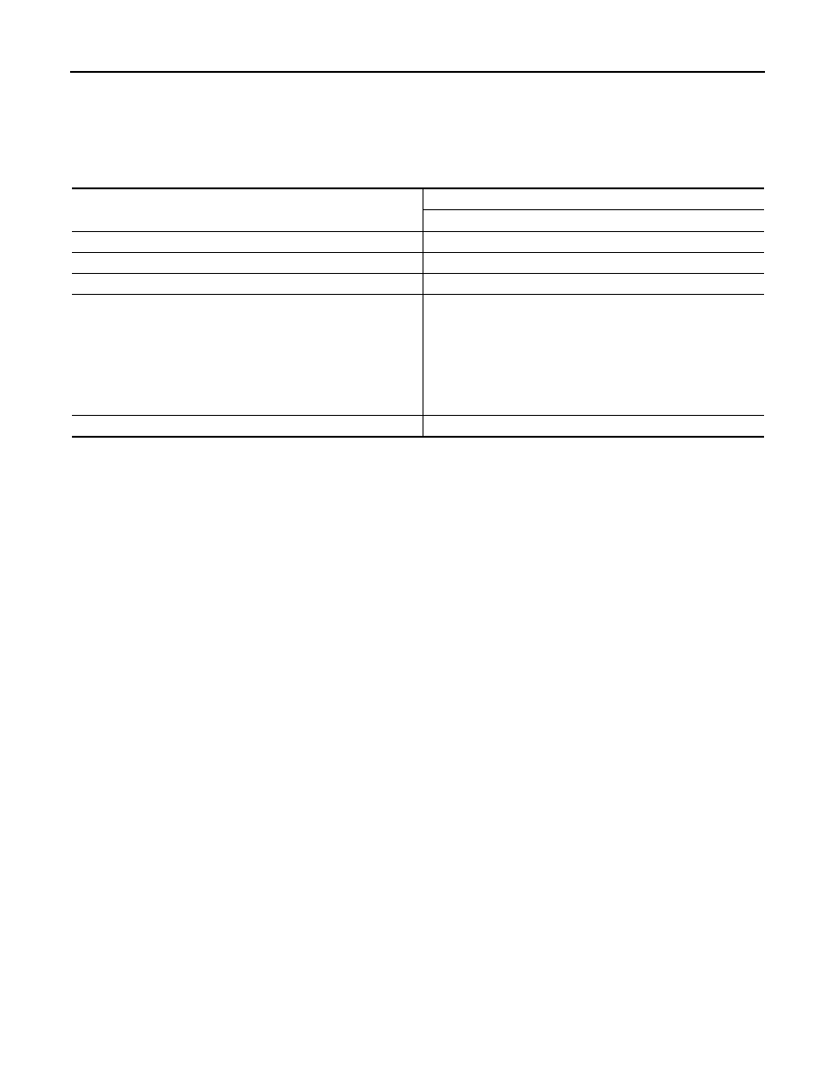
INFOID:0000000011278234

*: Always check with the Parts Department for the latest parts information.

Type*

VALEO

TG12C152-2617232

Nominal rating

[V - A]

14 - 120

Ground polarity

Negative

Working speed

[rpm]

1500 - 18,000

Hot output current (When 14 V is applied)

[A/rpm]

46/1,500
69/1,800
82/2,000
96/2,500

104/3,000

110/4,000
117/5,000

120/6,000

Regulated output voltage

[V]

14.3V at 20

°C

CO-1

ENGINE

C

D

E

F

G

H

I

J

K

L

M

SECTION 

CO

A

CO

N

O

P

CONTENTS

ENGINE COOLING SYSTEM

PRECAUTION ...............................................

2

PRECAUTIONS ...................................................

2

Precaution for Supplemental Restraint System 
(SRS) "AIR BAG" and "SEAT BELT PRE-TEN-
SIONER" .................................................................
..

2

PREPARATION ............................................

3

PREPARATION ...................................................

3

Special Service Tool  .................................................

3

Commercial Service Tools .......................................

3

SYSTEM DESCRIPTION  ..............................

4

DESCRIPTION ....................................................

4

Engine Cooling System .............................................

4

Engine Cooling System Schematic  ...........................

5

SYMPTOM DIAGNOSIS  ...............................

6

OVERHEATING CAUSE ANALYSIS ..................

6

Troubleshooting Chart ..............................................

6

PERIODIC MAINTENANCE ..........................

8

ENGINE COOLANT  ............................................

8

Inspection ..................................................................

8

Draining .....................................................................

8

Refilling .....................................................................

9

Flushing ...................................................................

11

RADIATOR .........................................................

12

RADIATOR CAP ........................................................

12

RADIATOR CAP : Inspection ..................................

12

RADIATOR ................................................................

12

RADIATOR : Inspection  ..........................................

12

REMOVAL AND INSTALLATION ...............

13

RADIATOR ........................................................

13

Exploded View .........................................................

13

Removal and Installation  .........................................

13

Inspection ................................................................

16

COOLING FAN ..................................................

17

Exploded View .........................................................

17

Removal and Installation  .........................................

17

Disassembly and Assembly .....................................

18

Inspection ................................................................

18

WATER PUMP  ..................................................

19

Exploded View .........................................................

19

Removal and Installation  .........................................

19

Inspection ................................................................

20

THERMOSTAT AND WATER CONTROL 
VALVE ...............................................................

21

Exploded View .........................................................

21

Removal and Installation  .........................................

21

Inspection ................................................................

22

WATER OUTLET AND WATER PIPING  ..........

23

Exploded View .........................................................

23

Removal and Installation  .........................................

23

SERVICE DATA AND SPECIFICATIONS 
(SDS) ............................................................

25

SERVICE DATA AND SPECIFICATIONS 
(SDS) .................................................................

25

Periodical Maintenance Specification ......................

25

Radiator ...................................................................

25

Thermostat ..............................................................

25

CO-2

< PRECAUTION >

PRECAUTIONS

PRECAUTION

PRECAUTIONS

Precaution for Supplemental Restraint System (SRS) "AIR BAG" and "SEAT BELT 
PRE-TENSIONER"

INFOID:0000000011279693

The Supplemental Restraint System such as “AIR BAG” and “SEAT BELT PRE-TENSIONER”, used along

with a front seat belt, helps to reduce the risk or severity of injury to the driver and front passenger for certain

types of collision. Information necessary to service the system safely is included in the SR and SB section of

this Service Manual.

WARNING:

• To avoid rendering the SRS inoperative, which could increase the risk of personal injury or death in

the event of a collision which would result in air bag inflation, all maintenance must be performed by

an authorized NISSAN/INFINITI dealer.

• Improper maintenance, including incorrect removal and installation of the SRS, can lead to personal

injury caused by unintentional activation of the system. For removal of Spiral Cable and Air Bag

Module, see the SR section.

• Do not use electrical test equipment on any circuit related to the SRS unless instructed to in this

Service Manual. SRS wiring harnesses can be identified by yellow and/or orange harnesses or har-

ness connectors.

PRECAUTIONS WHEN USING POWER TOOLS (AIR OR ELECTRIC) AND HAMMERS

WARNING:

• When working near the Airbag Diagnosis Sensor Unit or other Airbag System sensors with the Igni-

tion ON or engine running, DO NOT use air or electric power tools or strike near the sensor(s) with a

hammer. Heavy vibration could activate the sensor(s) and deploy the air bag(s), possibly causing

serious injury.

• When using air or electric power tools or hammers, always switch the Ignition OFF, disconnect the

battery and wait at least three minutes before performing any service.

PREPARATION

CO-3

< PREPARATION >

C

D

E

F

G

H

I

J

K

L

M

A

CO

N

P

O

PREPARATION

PREPARATION

Special Service Tool

INFOID:0000000011279694

The actual shape of the tools may differ from those illustrated here.

Commercial Service Tools

INFOID:0000000011279695

Tool number
(TechMate No.)
Tool name

Description

KV991J0070
(J-45695-A)
Coolant refill tool

Refilling engine cooling system

KV991J0010
(J-23688)
Engine coolant refractometer

Checking concentration of ethylene glycol in 
engine coolant

LMA053

WBIA0539E

Tool name

Description

Power tool

Loosening nuts, screws and bolts

Radiator cap tester

Checking radiator and radiator cap

Radiator cap tester adapter

Adapting radiator cap tester to radiator cap 
and radiator pipe (upper) filler neck
a: 28 (1.10) diameter
b: 31.4 (1.236) diameter
c: 41.3 (1.626) diameter
Unit: mm (in)

PIIB1407E

PBIC1982E

S-NT564


Content   ..  199  200  201  202   ..