Nissan Rogue. Manual - part 167
C1109 POWER AND GROUND SYSTEM
BRC-79
< DTC/CIRCUIT DIAGNOSIS >
[VDC/TCS/ABS]
C
D
E
G
H
I
J
K
L
M
A
B
BRC
N
O
P
Is the inspection result normal?
YES
>> GO TO 4.
NO
>> Repair or replace malfunctioning components.
4.
CHECK ABS ACTUATOR AND ELECTRIC UNIT (CONTROL UNIT) GROUND CIRCUIT
1. Turn ignition switch OFF.
2. Check continuity between ABS actuator and electric unit (control unit) connector E125 terminals 13, 38
and ground.
Is the inspection result normal?
YES
>> Replace ABS actuator and electric unit (control unit). Refer to
BRC-134, "Removal and Installa-
.
NO
>> Repair or replace malfunctioning components.
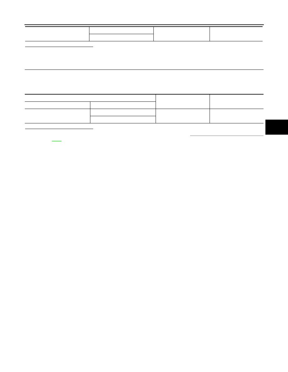
E125
1
—
Battery voltage
25
ABS actuator and electric unit (control unit)
—
Continuity
Connector
Terminal
E125
13
Ground
Yes
38