Content .. 1249 1250 1251 1252 ..
Nissan Rogue. Manual - part 1251
COMPONENT PARTS
WW-7
< SYSTEM DESCRIPTION >
C
D
E
F
G
H
I
J
K
M
A
B
WW
N
O
P
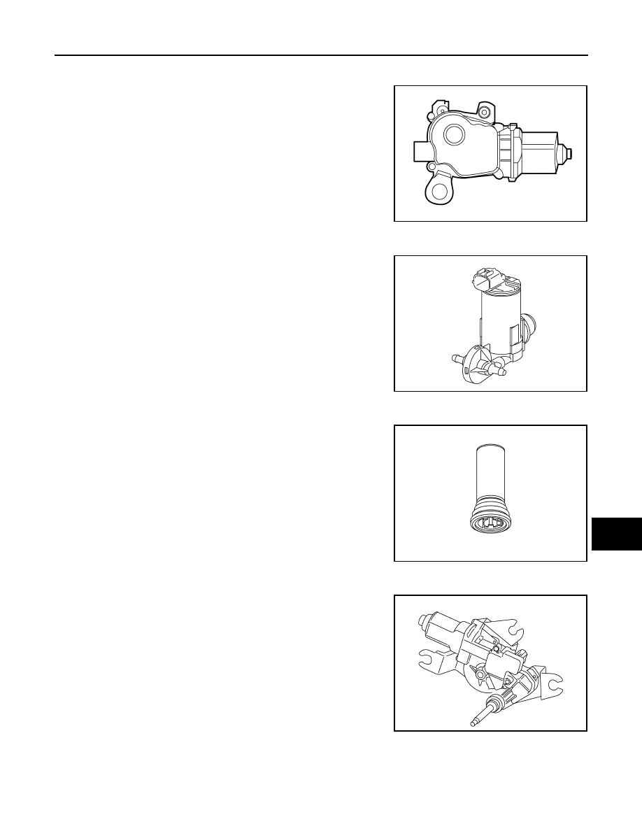
Front wiper motor
INFOID:0000000011280372
• Controls front wiper operation with IPDM E/R control.
• Transmits front wiper stop position signal to IPDM E/R.
Washer pump
INFOID:0000000011280373
• Washer fluid is sprayed according to washer switch states.
• Switching between front washer and rear washer is performed
according to the voltage polarity change to washer pump.
Washer fluid level switch
INFOID:0000000011280374
Detects that washer fluid level is low and transmits washer fluid level
switch signal to combination meter.
Rear wiper motor
INFOID:0000000011280375
• Controls rear wiper operation with BCM control.
• Transmits rear wiper stop position signal to BCM.
ALLIA1371ZZ
JMLIA2396ZZ
JMLIA2597ZZ
JMLIA2398ZZ