Nissan Rogue. Manual - part 1142


  Index      Nissan     Nissan Rogue (2015 year) - Service and Repair Manual


Search            


Content   ..  1140  1141  1142  1143   ..


Nissan Rogue. Manual - part 1142


ST-18

< SERVICE DATA AND SPECIFICATIONS (SDS) 

SERVICE DATA AND SPECIFICATIONS (SDS)

SERVICE DATA AND SPECIFICATIONS (SDS)

SERVICE DATA AND SPECIFICATIONS (SDS)

Steering Wheel

INFOID:0000000011280305

Unit: mm (in)

Steering Angle

INFOID:0000000011280306
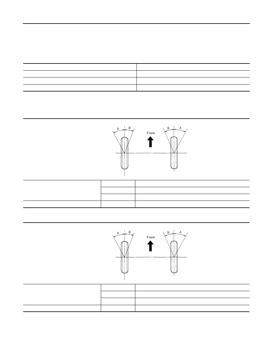
USA Production

Unit: Degree minute (Decimal degree)

Korea Production

Unit: Degree minute (Decimal degree)

Steering Column

INFOID:0000000011280307

STEERING COLUMN LENGTH

Item

Standard

Steering wheel axial end play

0 (0)

Steering wheel play

0 - 35 (0 - 1.38)

Steering wheel turning force

34 (3.5, 7.64) or less

Inner wheel angle (A)

Minimum

33

°25′ (33.42°)

Nominal

36

°25′ (36.42°)

Maximum

37

°25′ (37.42°)

Outer wheel angle (B)

Nominal

30

°45′ (30.75°)

SGIA0055E

Inner wheel angle (A)

Minimum

34

°00′ (34.00°)

Nominal

37

°00′ (37.00°)

Maximum

38

°00′ (38.00°)

Outer wheel angle (B)

Nominal

31

°00′ (31.00°)

SGIA0055E

SERVICE DATA AND SPECIFICATIONS (SDS)

ST-19

< SERVICE DATA AND SPECIFICATIONS (SDS) 

C

D

E

F

H

I

J

K

L

M

A

B

ST

N

O

P

Unit: mm (in)

STEERING COLUMN ROTATING TORQUE

 Unit: N·m (kg-m, in-lb)

TILT MECHANISM OPERATING RANGE

Unit: mm (in)

Steering Gear

INFOID:0000000011280308

STEERING OUTER SOCKET AND INNER SOCKET

INNER AND OUTER SOCKET LENGTH

RACK STROKE

Steering column length (with steering 
wheel installed)

Length (L)

577.2  (27.7)

Telescopic maximum

602.2  (23.7)

Telescopic minimum

552.2  (27.7)

Rotating torque

1.3 - 1.9 (0.13 - 0.19, 12 - 17)

Tilt operating range (L

1

)

44 (1.7)

Telescopic operating range (L

2

)

50 (2.0)

ALGIA0106ZZ

Outer socket

Swinging torque

0.3 - 2.9 N·m (0.03 - 0.30 kg-m, 3 - 26 in-lb)

Rotating torque

0.3 - 2.9 N·m (0.03 - 0.30 kg-m, 3 - 26 in-lb)

Axial end play

0.4 mm (0.02 in) or less

Inner socket

Swinging torque

7.8 - 16.7 N·m (0.80 - 1.7 kg-m, 69 - 148 in-lb)

Axial end play

0.4 mm (0.02 in) or less

Distance (A) from inner 
socket flat (B) to inner 
socket locknut (C)

A

17  mm  (0.67  in)

ALGIA0208ZZ

ST-20

< SERVICE DATA AND SPECIFICATIONS (SDS) 

SERVICE DATA AND SPECIFICATIONS (SDS)

RACK SLIDING FORCE

Rack stroke in neutral position (L)

74 mm (2.9 in)

AWGIA0003GB

Rack sliding force

105 - 165 N-f (10.7 - 16.8 kg-f, 23.6 - 37.1 lb-f)

STC-1

STEERING

C

D

E

F

H

I

J

K

L

M

SECTION 

STC

A

B

STC

N

O

P

CONTENTS

STEERING CONTROL SYSTEM

PRECAUTION ...............................................

3

PRECAUTIONS ...................................................

3

Precaution for Supplemental Restraint System 
(SRS) "AIR BAG" and "SEAT BELT PRE-TEN-
SIONER" .................................................................
..

3

Service Notice or Precautions for EPS System  ........

3

SYSTEM DESCRIPTION  ..............................

5

COMPONENT PARTS  ........................................

5

Component Parts Location ........................................

5

EPS Control Unit  .......................................................

6

EPS Motor, Torque Sensor, Reduction Gear ............

6

SYSTEM ..............................................................

7

EPS SYSTEM  ..............................................................

7

EPS SYSTEM : System Description .........................

7

EPS SYSTEM : Fail-Safe ..........................................

8

EPS SYSTEM : Protection Function .........................

8

DIAGNOSIS SYSTEM (EPS CONTROL UNIT) 

.....

9

CONSULT Function  ..................................................

9

ECU DIAGNOSIS INFORMATION  ..............

11

EPS CONTROL UNIT .........................................

11

Reference Value  .....................................................

11

Fail-Safe ..................................................................

13

Protection Function  .................................................

13

DTC Inspection Priority Chart .................................

13

DTC Index  ...............................................................

13

WIRING DIAGRAM ......................................

14

EPS SYSTEM  .....................................................

14

Wiring Diagram  .......................................................

14

BASIC INSPECTION  ...................................

19

DIAGNOSIS AND REPAIR WORKFLOW  .........

19

Work Flow ................................................................

19

DTC/CIRCUIT DIAGNOSIS  .........................

20

C1601 BATTERY POWER SUPPLY  ................

20

DTC Logic ................................................................

20

Diagnosis Procedure  ...............................................

20

C1604 TORQUE SENSOR ................................

23

DTC Logic ................................................................

23

Diagnosis Procedure  ...............................................

23

C1606 EPS MOTOR ..........................................

24

DTC Logic ................................................................

24

Diagnosis Procedure  ...............................................

24

C1607, C1608 EPS CONTROL UNIT  ...............

25

DTC Logic ................................................................

25

Diagnosis Procedure  ...............................................

25

C1609 VEHICLE SPEED SIGNAL ....................

26

DTC Logic ................................................................

26

Diagnosis Procedure  ...............................................

26

U1000 CAN COMM CIRCUIT  ...........................

27

Description ...............................................................

27

DTC Logic ................................................................

27

Diagnosis Procedure  ...............................................

27

EPS WARNING LAMP ......................................

28

Component Function Check  ....................................

28

Diagnosis Procedure  ...............................................

28

SYMPTOM DIAGNOSIS  ..............................

29

EPS WARNING LAMP DOES NOT TURN ON ...

29

Description ...............................................................

29

Diagnosis Procedure  ...............................................

29

EPS WARNING LAMP DOES NOT TURN 
OFF ....................................................................

30

Description ...............................................................

30

Diagnosis Procedure  ...............................................

30


Content   ..  1140  1141  1142  1143   ..