Content .. 1001 1002 1003 1004 ..
Nissan Rogue. Manual - part 1003
REAR DRIVE SHAFT
RAX-19
< REMOVAL AND INSTALLATION >
[AWD]
C
E
F
G
H
I
J
K
L
M
A
B
RAX
N
O
P
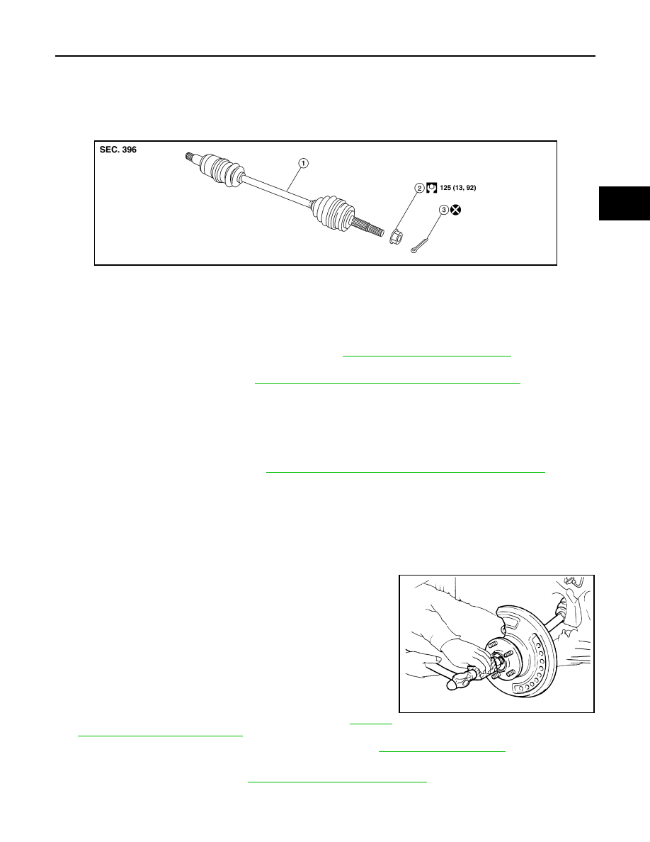
REAR DRIVE SHAFT
Exploded View
INFOID:0000000011280328
REMOVAL
Removal and Installation
INFOID:0000000011280329
REMOVAL
1. Remove the wheel and tire using power tool. Refer to
WT-67, "Removal and Installation"
.
2. Remove the bolt and separate the rear wheel sensor from the axle housing. Position the rear wheel sen-
sor and the harness aside. Refer to
BRC-131, "REAR WHEEL SENSOR : Exploded View"
.
CAUTION:
• Failure to remove the rear speed sensor from the axle housing may result in damage to the rear
wheel sensor.
• Pull out the rear wheel sensor, being careful to turn it as little as possible. do not pull on wheel
sensor harness.
3. Remove brake caliper torque member bolts using power tool, leaving the brake hose attached. Position
brake caliper aside with wire. Refer to
BR-47, "BRAKE CALIPER ASSEMBLY : Exploded View"
CAUTION:
Do not depress brake pedal while brake caliper is removed.
4. Put alignment marks on the disc brake rotor and the wheel hub and bearing. Remove the disc brake rotor.
CAUTION:
Do not drop the disc brake rotor.
5. Remove the cotter pin.
6. Loosen but do not remove, the wheel hub lock nut from the drive shaft using power tool.
7. Tap the wheel hub lock nut with a piece of wood and suitable
tool to disengage the drive shaft from the wheel hub and bear-
ing.
CAUTION:
• Do not place drive shaft joint at an extreme angle. Be
careful not to overextend slide joint.
• Do not allow the drive shaft to hang without support.
NOTE:
Use a suitable puller if the drive shaft cannot be separated from
the wheel hub and bearing.
8. Remove the wheel hub lock nut.
9. Remove the coil spring and spring seats. Refer to
"Removal and Installation - AWD"
10. Remove the bolts and the suspension member stay. Refer to
.
11. Remove drive shaft from final drive.
12. Remove the side oil seal. Refer to
DLN-114, "Removal and Installation"
.
INSPECTION AFTER REMOVAL
1.
Drive shaft
2.
Wheel hub lock nut
3.
Cotter pin
AWDIA1178ZZ
JPDIG0070ZZ