Nissan Rogue. Manual - part 83


  Index      Nissan     Nissan Rogue (2015 year) - Service and Repair Manual


Search            


Content   ..  81  82  83  84   ..


Nissan Rogue. Manual - part 83


AV-324

< DTC/CIRCUIT DIAGNOSIS >

[NAVIGATION WITH BOSE]

U12B1 POWER SUPPLY VOLTAGE

U12B1 POWER SUPPLY VOLTAGE

DTC Logic

INFOID:0000000011276994

DTC DETECTION LOGIC

Diagnosis Procedure

INFOID:0000000011276995

1.

CHECK CHARGING SYSTEM

Check the vehicle charging system. Refer to 

CHG-11, "Work Flow (With EXP-800 NI or GR8-1200 NI)"

 or

CHG-14, "Work Flow (Without EXP-800 NI or GR8-1200 NI)"

.

Is the inspection result normal?

YES

>> Replace the AV control unit. Refer to 

AV-369, "Removal and Installation"

.

NO

>> Repair or replace the malfunctioning components.
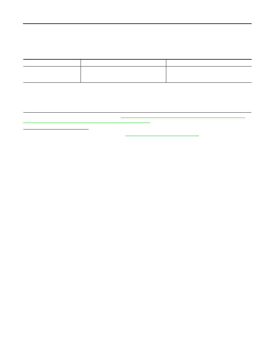
CONSULT Display

DTC Detection Condition

Possible Cause

Supply Voltage Goes High > 
16V for 20s
[U12B1]

AV control unit supply voltage exceeds upper lim-
its.

Charging system malfunction.

AV

U1300 AV COMM CIRCUIT

AV-325

< DTC/CIRCUIT DIAGNOSIS >

[NAVIGATION WITH BOSE]

C

D

E

F

G

H

I

J

K

L

M

B

A

O

P

U1300 AV COMM CIRCUIT

DTC Logic

INFOID:0000000011276996

DTC DETECTION LOGIC

Diagnosis Procedure

INFOID:0000000011276997

1.

PERFORM SELF DIAGNOSTIC RESULT FOR METER M&A

1. Turn ignition switch ON and wait for 2 seconds or more.

2. Perform “Self Diagnostic Result” for “METER M&A”. 
Are any DTCs displayed?

YES

>> Refer to 

MWI-31, "DTC Index"

.

NO

>> GO TO 2.

2.

CHECK AV COMMUNICATION CIRCUIT (MCAN L) CONTINUITY

1. Turn ignition switch OFF.

2. Disconnect AV control unit connector M109 and combination meter connector M77.

3. Check continuity between AV control unit connector M109 and combination meter connector M77.

4. Check continuity between AV control unit connector M109 and ground.

Is the inspection result normal?

YES

>> GO TO 3.

NO

>> Repair or replace harness or connectors.

3.

CHECK AV COMMUNICATION CIRCUIT (MCAN H) CONTINUITY

1. Check continuity between AV control unit connector M109 and combination meter connector M77.

2. Check continuity between AV control unit connector M109 and ground.

CONSULT Display

DTC Detection Condition

Possible Cause

AV COMM CIRCUIT
[U1300]

AV communication circuit malfunction (MCAN) 
between AV control unit and combination meter.

AV communication circuits between AV control 
unit and combination meter.

AV control unit

Combination meter

Continuity

Connector

Terminal

Connector

Terminal

M109

32

M77

48

Yes

39

AV control unit

Ground

Continuity

Connector

Terminal

M109

32

No

39

AV control unit

Combination meter

Continuity

Connector

Terminal

Connector

Terminal

M109

31

M77

47

Yes

38

AV control unit

Ground

Continuity

Connector

Terminal

M109

31

No

38

AV-326

< DTC/CIRCUIT DIAGNOSIS >

[NAVIGATION WITH BOSE]

U1300 AV COMM CIRCUIT

Is the inspection result normal?

YES

>> Replace the AV control unit. Refer to 

AV-369, "Removal and Installation"

.

NO

>> Repair or replace harness or connectors.

AV

U1304 CAMERA IMAGE CALIBRATION

AV-327

< DTC/CIRCUIT DIAGNOSIS >

[NAVIGATION WITH BOSE]

C

D

E

F

G

H

I

J

K

L

M

B

A

O

P

U1304 CAMERA IMAGE CALIBRATION

DTC Logic

INFOID:0000000011276998

DTC DETECTION LOGIC

Diagnosis Procedure

INFOID:0000000011276999

1.

PERFORM CALIBRATION

When U1304 is detected, perform calibration of camera image.

>> Refer to 

AV-284, "CALIBRATING CAMERA IMAGE (AROUND VIEW MONITOR) : Work Proce-

dure"

.

CONSULT Display

DTC Detection Condition

Possible Cause

Non-completion of the calibra-
tion
[U1304]

Camera image calibration is incomplete.

Perform calibration of camera image.


Content   ..  81  82  83  84   ..