Nissan Maxima. Manual - part 961
POWER SUPPLY AND GROUND CIRCUIT
RF-17
< DTC/CIRCUIT DIAGNOSIS >
[WITH SINGLE PANEL SUNROOF]
C
D
E
F
G
H
I
J
L
M
A
B
RF
N
O
P
NO
>> GO TO 9
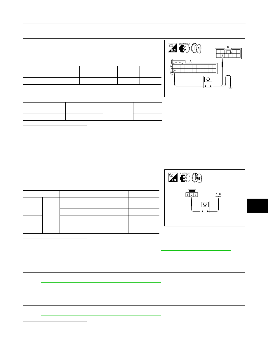
9.
CHECK COMBINATION METER CIRCUIT
1. Turn ignition switch OFF.
2. Disconnect combination meter.
3. Check continuity between combination meter connector (A) and
sunroof motor assembly connector (B).
4. Check continuity between combination meter connector (A) and
ground.
Is the inspection result normal?
YES
>> Replace combination meter. Refer to
MWI-122, "Removal and Installation"
NO
>> Repair or replace harness.
SUNROOF MOTOR ASSEMBLY : Component Inspection
INFOID:0000000009465672
SUNROOF SWITCH
1.
CHECK SUNROOF SWITCH
1. Turn ignition switch OFF.
2. Disconnect sunroof switch.
3. Check continuity between sunroof switch terminals.
Is the inspection result normal?
YES
>> Sunroof switch is OK.
NO
>> Replace sunroof switch (map lamp assembly). Refer to
INL-84, "Removal and Installation"
SUNROOF MOTOR ASSEMBLY : Special Repair Requirement
INFOID:0000000009465673
1.
PERFORM INITIALIZATION PROCEDURE
Perform initialization procedure.
RF-7, "BASIC INSPECTION : Special Repair Requirement"
.
>> GO TO 2
2.
CHECK ANTI-PINCH OPERATION
Check anti-pinch operation.
RF-7, "BASIC INSPECTION : Special Repair Requirement"
.
Is the inspection result normal?
YES
>> Inspection End.
NO
>> Check fitting adjustment. Refer to
Combination
meter connector
Terminal
Sunroof motor as-
sembly connector
Terminal
Continuity
M24 (A)
30
R5 (B)
9
Yes
Combination meter
connector
Terminal
Ground
Continuity
M24 (A)
30
No
AWKIA1413ZZ
Terminals
Condition
Continuity
1
2
Sunroof switch is operated
TILT DOWN or SLIDE OPEN
Yes
Other than above
No
3
Sunroof switch is operated
TILT UP or SLIDE CLOSE
Yes
Other than above
No
ALKIA0268ZZ