Nissan Maxima. Manual - part 893


  Index      Nissan     Nissan Maxima (2009-2014 year) - Service and Repair Manual


Search            


Content   ..  891  892  893  894   ..


Nissan Maxima. Manual - part 893


PCS-52

< DTC/CIRCUIT DIAGNOSIS >

[POWER DISTRIBUTION SYSTEM]

B2614 ACC RELAY CIRCUIT

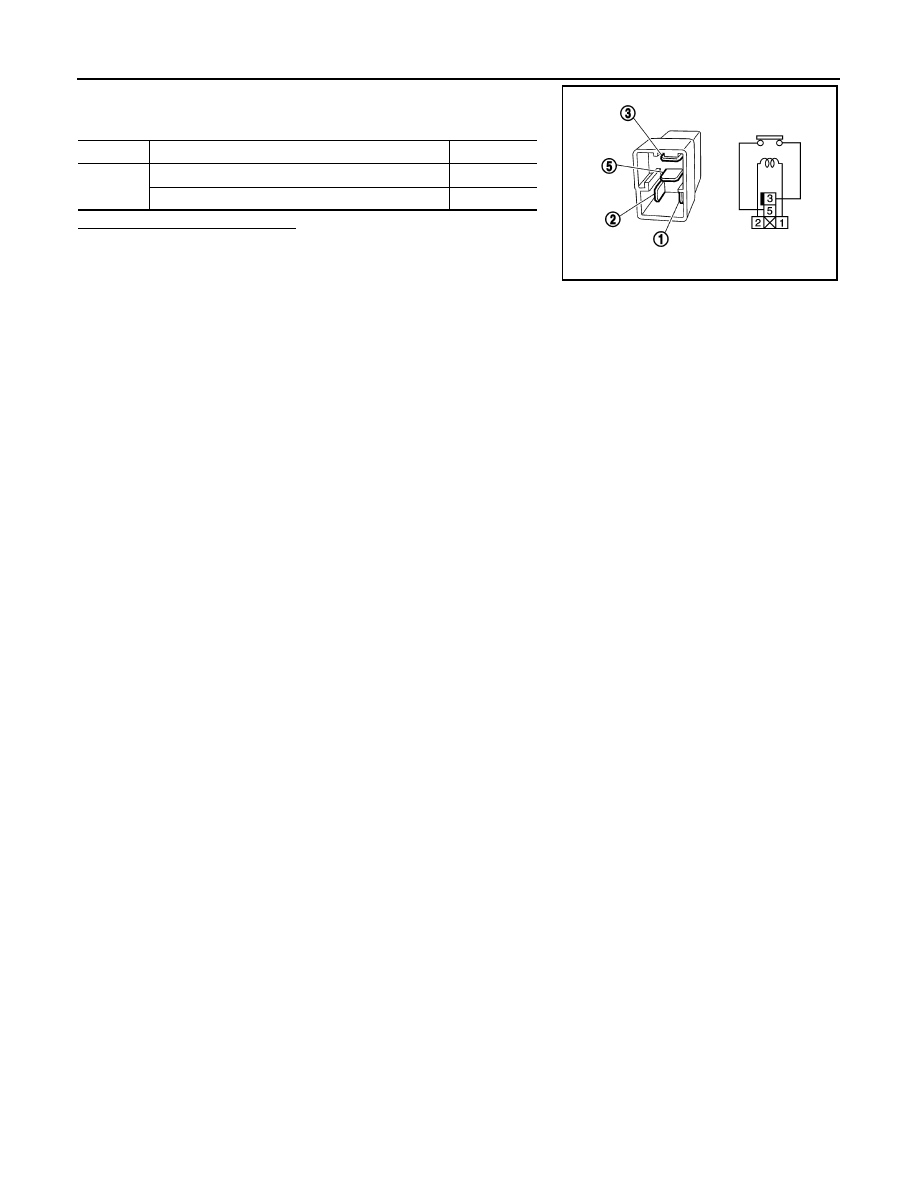
3. Check the continuity between accessory relay-1 terminals under

the following conditions.

Is the inspection result normal?

YES

>> Inspection End.

NO

>> Replace accessory relay-1.

Terminals

Condition

Continuity

3 and 5

12V direct current supply between terminals 1 and 2

Yes

No current supply

No

PBIB0098E

PCS

B2615 FRONT BLOWER MOTOR RELAY CIRCUIT

PCS-53

< DTC/CIRCUIT DIAGNOSIS >

[POWER DISTRIBUTION SYSTEM]

C

D

E

F

G

H

I

J

K

L

B

A

O

P

N

B2615 FRONT BLOWER MOTOR RELAY CIRCUIT

Description

INFOID:0000000010049433

BCM controls the various electrical components and simultaneously supplies power according to the power

supply position.

BCM checks the power supply position internally.

DTC Logic

INFOID:0000000010049434

DTC DETECTION LOGIC

DTC CONFIRMATION PROCEDURE

1.

 PERFORM DTC CONFIRMATION PROCEDURE

1. Turn ignition switch ON under the following conditions, and wait for at least 1 second.

-

CVT selector lever is in the P or N position.

-

Release brake pedal.

2. Check “Self diagnostic result” with CONSULT. 
Is DTC detected?

YES

>> Go to 

PCS-53, "Diagnosis Procedure"

.

NO

>> Inspection End.

Diagnosis Procedure

INFOID:0000000010049435

Regarding Wiring Diagram information, refer to 

PCS-103, "Wiring Diagram"

.

1.

CHECK FRONT BLOWER MOTOR RELAY POWER SUPPLY

1. Turn ignition switch OFF.

2. Disconnect front blower motor relay.

3. Check voltage between front blower motor relay harness con-

nector and ground under the following conditions.

Is the inspection result normal?

YES

>> GO TO 3

NO

>> GO TO 2

2.

 CHECK FRONT BLOWER MOTOR RELAY POWER SUPPLY CIRCUIT

1. Turn ignition switch OFF.

2. Disconnect BCM harness connector.

3. Check continuity between front blower motor relay harness connector and BCM harness connector.

DTC No.

Trouble diagnosis 

name

DTC detecting condition

Possible cause

B2615

Front blower motor 
relay circuit

BCM detects a difference of signal for 1 second or 
more between the following information.
• Front blower motor relay ON/OFF request 
• Front blower motor relay feedback

• Harness or connectors 

(Front blower motor relay circuit is 
open or shorted)

• Front blower motor relay

Front blower 

motor relay

Ground

Condition

Voltage (V)

Terminal

2

Ground

OFF or ACC

0

ON

Battery voltage

ALMIA0450ZZ

PCS-54

< DTC/CIRCUIT DIAGNOSIS >

[POWER DISTRIBUTION SYSTEM]

B2615 FRONT BLOWER MOTOR RELAY CIRCUIT

4. Check continuity between front blower motor relay harness connector and ground.

Is the inspection result normal?

YES

>> GO TO 6

NO

>> Repair or replace harness.

3.

 CHECK FRONT BLOWER MOTOR RELAY GROUND CIRCUIT

1. Turn ignition switch OFF.

2. Check continuity between front blower motor relay harness con-

nector and ground.

Is the inspection result normal?

YES

>> GO TO 4

NO

>> Repair front blower motor relay ground circuit.

4.

CHECK FRONT BLOWER MOTOR RELAY POWER SUPPLY CIRCUIT-2

Check voltage between front blower motor relay harness connector

and ground.

Is the inspection result normal?

YES

>> GO TO 5

NO

>> Repair or replace harness.

5.

 CHECK FRONT BLOWER MOTOR RELAY

Refer to 

PCS-54, "Component Inspection (Front Blower Motor Relay)"

.

Is the inspection result normal?

YES

>> GO TO 6

NO

>> Replace front blower motor relay.

6.

 CHECK INTERMITTENT INCIDENT

Refer to 

GI-41, "Intermittent Incident"

.

>> Inspection End.

Component Inspection (Front Blower Motor Relay)

INFOID:0000000010049436

1.

CHECK FRONT BLOWER MOTOR RELAY

1. Turn ignition switch OFF.

2. Remove front blower motor relay.

Front blower motor relay

BCM

Continuity

Terminal

Connector

Terminal

2

M19

90

Yes

Front blower motor relay

Ground

Continuity

Terminal

2

Ground

No

Front blower motor relay

Ground

Continuity

Terminal

1

Ground

Yes

ALMIA0445ZZ

Front blower motor relay

Ground

Voltage (V)

Terminal

3

Ground

Battery voltage

ALMIA0441ZZ

PCS

B2615 FRONT BLOWER MOTOR RELAY CIRCUIT

PCS-55

< DTC/CIRCUIT DIAGNOSIS >

[POWER DISTRIBUTION SYSTEM]

C

D

E

F

G

H

I

J

K

L

B

A

O

P

N

3. Check the continuity between front blower motor relay terminals

under the following conditions.

Is the inspection result normal?

YES

>> Inspection End.

NO

>> Replace front blower motor relay.

Terminals

Condition

Continuity

3 and 5

12V direct current supply between terminals 1 and 2

Yes

No current supply

No

PBIB0098E


Content   ..  891  892  893  894   ..