Nissan Maxima. Manual - part 864
MWI
BCM (BODY CONTROL MODULE)
MWI-71
< ECU DIAGNOSIS INFORMATION >
C
D
E
F
G
H
I
J
K
L
M
B
A
O
P
103
(V)
Ground Trunk lid opening.
Output Trunk lid
Open (trunk lid opener ac-
tuator is activated)
Battery voltage
Close (trunk lid opener ac-
tuator is not activated)
0V
110
(V/W)
Ground Trunk room lamp
Output Trunk room lamp
ON
0V
OFF
Battery voltage
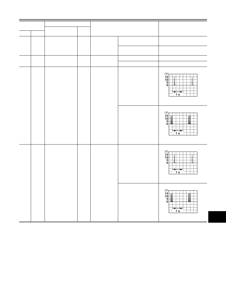
114
(B)
Ground
Trunk room antenna
1 (-)
Output
Ignition switch
OFF
When Intelligent Key is in
the passenger compart-
ment
When Intelligent Key is not
in the passenger compart-
ment
115
(W)
Ground
Trunk room antenna
1 (+)
Output
Ignition switch
OFF
When Intelligent Key is in
the passenger compart-
ment
When Intelligent Key is not
in the passenger compart-
ment
Terminal No.
(Wire color)
Description
Condition
Value
(Approx.)
Signal name
Input/
Output
(+)
(-)
JMKIA0062GB
JMKIA0063GB
JMKIA0062GB
JMKIA0063GB