Nissan Maxima. Manual - part 836


  Index      Nissan     Nissan Maxima (2009-2014 year) - Service and Repair Manual


Search            


Content   ..  834  835  836  837   ..


Nissan Maxima. Manual - part 836


MA-18

< PERIODIC MAINTENANCE >

RECOMMENDED FLUIDS AND LUBRICANTS

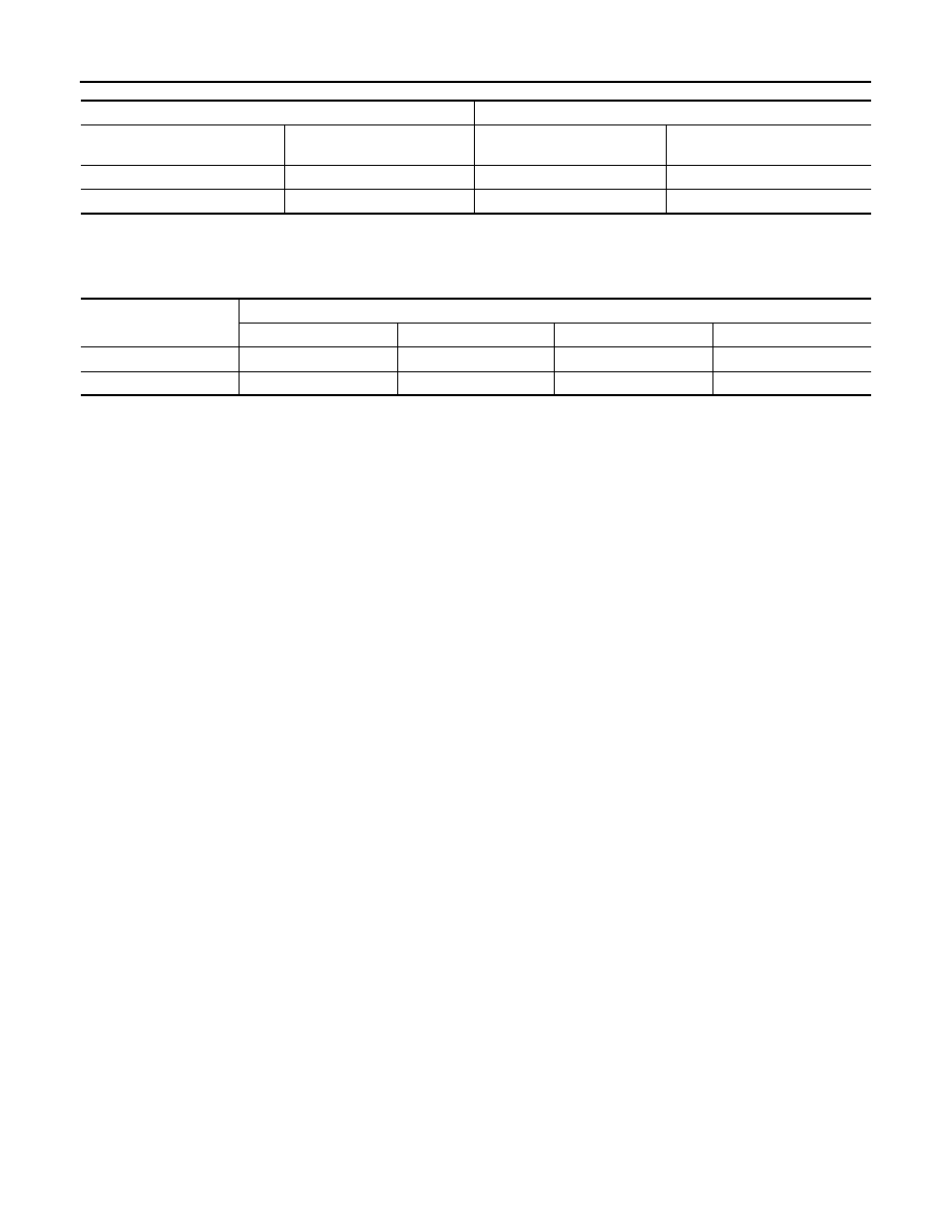
Coolant Mixture Ratios

When checking the engine coolant mixture ratio by the coolant hydrometer, use the chart below to correct your

hydrometer reading (specific gravity) according to coolant temperature.

Mixed Coolant Specific Gravity

Unit: specific gravity

WARNING:

Do not remove the radiator cap when the engine is hot. Serious burns could be caused by high pres-

sure fluid escaping from the radiator. Wait until the engine and radiator cool down.

CAUTION:

• When adding or replacing coolant, be sure to use only Genuine NISSAN Engine Coolant or equiva-

lent in its quality with the proper mixture ratio.

• The use of other types of engine coolant may damage your cooling system. 

For outside temperatures down to:

Anti-freeze coolant mixture ratio

° C

° F

Genuine NISSAN Engine 

Coolant or equivalent

Demineralized water or distilled 

water

– 15

°

5

°

30 %

70 %

– 35

°

– 30

°

50 %

50 %

Engine coolant mixture 

ratio

Coolant temperature 

°C (°F)

15

° (59°)

25

° (77°)

35

° (95°)

45

° (113°)

30%

1.046 - 1.050

1.042 - 1.046

1.038 - 1.042

1.033 - 1.038

50%

1.076 - 1.080

1.070 - 1.076

1.065 - 1.071

1.059 - 1.065

ENGINE MAINTENANCE (VQ35DE)

MA-19

< PERIODIC MAINTENANCE >

C

D

E

F

G

H

I

J

K

L

M

B

MA

N

O

A

ENGINE MAINTENANCE (VQ35DE)

DRIVE BELTS
DRIVE BELTS : Checking Drive Belts

INFOID:0000000009471110

WARNING:

Inspect and check the drive belts with the engine off.

• Check that the indicator of drive belt auto-tensioner is within the possible use range.

NOTE:

• Check the drive belt auto-tensioner indication when the engine is cold.

• When new drive belt is installed, the indicator should be within the new drive belt range.

• Visually check entire drive belt for wear, damage or cracks.

• If the indicator is out of the possible use range or the drive belt is damaged, replace the drive belt.

DRIVE BELTS : Tension Adjustment

INFOID:0000000009471111

• Belt tension is not manually adjustable, it is automatically adjusted by the drive belt auto-tensioner.

ENGINE COOLANT
ENGINE COOLANT : System Inspection

INFOID:0000000009471112

WARNING:

• Do not remove the radiator cap when the engine is hot. Serious burns could occur from high pres-

sure coolant escaping from the radiator.

• Wrap a thick cloth around the cap. Slowly push down and turn it a quarter turn to allow built-up pres-

sure to escape. Carefully remove the cap by pushing down and turning it all the way.

CHECKING COOLING SYSTEM HOSES

Check hoses for the following:

• Improper attachment

• Leaks

• Cracks

• Damage

• Loose connections

JPBIA1625ZZ

1.

Idler pulley

2.

Drive belt

3.

Power steering oil pump

4.

Drive belt auto-tensioner

5.

Crankshaft pulley

6.

Idler pulley

7.

A/C compressor

8.

Generator

A.

Indicator

B.

New drive belt range

C.

Possible use range

D.

View D

Engine front

MA-20

< PERIODIC MAINTENANCE >

ENGINE MAINTENANCE (VQ35DE)

• Chafing

• Deterioration

CHECKING RESERVOIR TANK LEVEL

• Check if the reservoir tank coolant level is within MIN to MAX

range when the engine is cool.

• Adjust coolant level if it is too much or too little.

ENGINE COOLANT : Changing Engine Coolant

INFOID:0000000009471113

WARNING:

• To avoid being scalded, do not change the coolant when the engine is hot.

• Wrap a thick cloth around cap and carefully remove the cap. First, turn the cap a quarter of a turn to

release built-up pressure. Then turn the cap all the way.

DRAINING ENGINE COOLANT

1. Remove the engine under cover. Refer to 

EM-23, "Removal and Installation"

.

2. Open radiator drain plug at the bottom of radiator and remove the radiator filler cap. This is the only step

required for a partial cooling system drain. 

CAUTION:

Do not allow the coolant to contact drive belt.

3. If removing the heater core, remove the upper heater hose from the engine coolant outlet and apply mod-

erate air pressure of 103.46 kPa (1.055 kg-cm

2

, 15 psi) maximum for 30 seconds into the hose to blow out

excess coolant from the core.

4. For a complete cooling system drain, remove the reservoir tank and drain the coolant, and then clean the

reservoir tank before installation.

CAUTION:

Do not allow the coolant to contact drive belt.

5. When performing a complete cooling system drain remove the cylinder block front drain plug and the cyl-

inder block RH drain plug.

6. Check the drained coolant for contaminants such as rust, corrosion or discoloration.

• If contaminated, flush the engine cooling system. 

REFILLING ENGINE COOLANT

1. Install the radiator drain plug. If the cooling system was drained completely, install the reservoir tank and

the cylinder block drain plugs.

• The radiator must be completely empty of coolant and water.

• Apply sealant to the threads of the cylinder block drain plugs. Use Genuine High Performance Thread

Sealant or equivalent. Refer to 

GI-21, "Recommended Chemical Products and Sealants"

.

2. If disconnected, reattach the upper radiator hose at the engine side.
3. Set the vehicle heater controls to the full HOT and heater ON position. Turn the vehicle ignition ON with

the engine OFF as necessary to activate the heater mode.

SMA412B

Radiator drain plug

: Refer to 

CO-14, "Removal and Installation"

.

Cylinder block front drain plug

: 9.8 N·m (1.0 kg-m, 87 in-lb)

Cylinder block RH drain plug

: 19.6 N·m (2.0 kg-m, 14 ft-lb)

ENGINE MAINTENANCE (VQ35DE)

MA-21

< PERIODIC MAINTENANCE >

C

D

E

F

G

H

I

J

K

L

M

B

MA

N

O

A

4. Install the Tool by installing the radiator cap adapter onto the

radiator neck opening. Then attach the gauge body assembly

with the refill tube and the venturi assembly to the radiator cap

adapter.

5. Insert the refill hose into the coolant mixture container that is

placed at floor level. Make sure the ball valve is in the closed

position. 

• Use recommended coolant or equivalent. 

Refer to 

MA-16, "FOR USA AND CANADA : Anti-Freeze Cool-

ant Mixture Ratio"

 (United States and Canada) or 

MA-17,

"FOR MEXICO : Engine Coolant Mixture Ratio"

 (Mexico).

CAUTION:

Do not use any cooling system additives such as radiator

sealer. Additives may clog the cooling system and cause

damage to the engine, transmission and/or cooling system.

6. Install an air hose to the venturi assembly, the air pressure must be within specification. 

CAUTION:

The compressed air supply must be equipped with an air dryer.

7. The vacuum gauge will begin to rise and there will be an audible hissing noise. During this process open

the ball valve on the refill hose slightly. Coolant will be visible rising in the refill hose. Once the refill hose is

full of coolant, close the ball valve. This will purge any air trapped in the refill hose.

8. Continue to draw the vacuum until the gauge reaches 28 inches

of vacuum. The gauge may not reach 28 inches in high altitude

locations; use the vacuum specifications based on the altitude

above sea level.

9. When the vacuum gauge has reached the specified amount, disconnect the air hose and wait 20 seconds

to see if the system loses any vacuum. If the vacuum level drops, perform any necessary repairs to the

system and repeat steps 6 - 8 to bring the vacuum to the specified amount. Recheck for any leaks. 

10. Place the coolant container (with the refill hose inserted) at the same level as the top of the radiator. Then

open the ball valve on the refill hose so the coolant will be drawn up to fill the cooling system. The cooling

system is full when the vacuum gauge reads zero.

CAUTION:

Do not allow the coolant container to get too low when filling, to avoid air from being drawn into

the cooling system. 

11. Remove the Tool from the radiator neck opening.

Tool number

: KV991J0070 (J-45695)

Engine coolant capacity 
(with reservoir tank)

: Refer to 

MA-15, "FOR 

USA AND CANADA : Flu-
ids and Lubricants"

 (Unit-

ed States and Canada) or 

MA-16, "FOR MEXICO : 
Fluids and Lubricants"


(Mexico).

LLIA0058E

Compressed air supply pressure : 549 - 824 kPa (5.6 - 8.4 kg/cm

2

, 80 - 119 psi)

Altitude above sea level

Vacuum gauge reading

0 - 100 m (328 ft)

: 28 inches of vacuum

300 m (984 ft)

: 27 inches of vacuum

500 m (1,641 ft)

: 26 inches of vacuum

1,000 m (3,281 ft)

: 24 - 25 inches of vacuum

LLIA0057E


Content   ..  834  835  836  837   ..