Nissan Maxima. Manual - part 815


  Index      Nissan     Nissan Maxima (2009-2014 year) - Service and Repair Manual


Search            


Content   ..  813  814  815  816   ..


Nissan Maxima. Manual - part 815


LAN-72

< DTC/CIRCUIT DIAGNOSIS >

[CAN SYSTEM (TYPE 2)]

MAIN LINE BETWEEN DLC AND HVAC CIRCUIT

DTC/CIRCUIT DIAGNOSIS

MAIN LINE BETWEEN DLC AND HVAC CIRCUIT

Diagnosis Procedure

INFOID:0000000009990306

1.

CHECK HARNESS CONTINUITY (OPEN CIRCUIT)

1. Turn the ignition switch OFF.

2. Disconnect the battery cable from the negative terminal.

3. Disconnect the following harness connectors.

-

ECM

-

A/C auto amp.

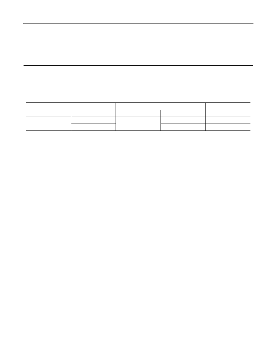
4. Check the continuity between the data link connector and the A/C auto amp. harness connector.

Is the inspection result normal?

YES (Present error)>>Check CAN system type decision again.

YES (Past error)>>Error was detected in the main line between the data link connector and the A/C auto

amp. 

NO

>> Repair the main line between the data link connector and the A/C auto amp.

Data link connector

A/C auto amp. harness connector

Continuity

Connector No.

Terminal No.

Connector No.

Terminal No.

M22

6

M37

1

Existed

14

2

Existed

LAN

MAIN LINE BETWEEN HVAC AND A-BAG CIRCUIT

LAN-73

< DTC/CIRCUIT DIAGNOSIS >

[CAN SYSTEM (TYPE 2)]

C

D

E

F

G

H

I

J

K

L

B

A

O

P

N

MAIN LINE BETWEEN HVAC AND A-BAG CIRCUIT

Diagnosis Procedure

INFOID:0000000009990307

1.

CHECK HARNESS CONTINUITY (OPEN CIRCUIT)

1. Turn the ignition switch OFF.

2. Disconnect the battery cable from the negative terminal.

3. Disconnect the following harness connectors.

-

A/C auto amp.

-

Harness connectors M1 and E30

4. Check the continuity between the A/C auto amp. harness connector and the harness connector.

Is the inspection result normal?

YES (Present error)>>Check CAN system type decision again.

YES (Past error)>>Error was detected in the main line between the A/C auto amp. and the air bag diagnosis

sensor unit.

NO

>> Repair the main line between the A/C auto amp. and the air bag diagnosis sensor unit.

A/C auto amp. harness connector

Harness connector

Continuity

Connector No.

Terminal No.

Connector No.

Terminal No.

M37

1

M1

15G

Existed

2

8G

Existed

LAN-74

< DTC/CIRCUIT DIAGNOSIS >

[CAN SYSTEM (TYPE 2)]

MAIN LINE BETWEEN A-BAG AND ABS CIRCUIT

MAIN LINE BETWEEN A-BAG AND ABS CIRCUIT

Diagnosis Procedure

INFOID:0000000009990308

1.

CHECK CONNECTOR

1. Turn the ignition switch OFF.

2. Disconnect the battery cable from the negative terminal.

3. Check the following terminals and connectors for damage, bend and loose connection (connector side

and harness side).

-

Harness connector M1

-

Harness connector E30

Is the inspection result normal?

YES

>> GO TO 2.

NO

>> Repair the terminal and connector.

2.

CHECK HARNESS CONTINUITY (OPEN CIRCUIT)

1. Disconnect the following harness connectors.

-

A/C auto amp.

-

Harness connectors M1 and E30

2. Check the continuity between the A/C auto amp. harness connector and the harness connector.

Is the inspection result normal?

YES

>> GO TO 3.

NO

>> Repair the main line between the air bag diagnosis sensor unit and the harness connector M1.

3.

CHECK HARNESS CONTINUITY (OPEN CIRCUIT)

1. Disconnect the connector of ABS actuator and electric unit (control unit).

2. Check the continuity between the harness connector and the ABS actuator and electric unit (control unit)

harness connector.

Is the inspection result normal?

YES (Present error)>>Check CAN system type decision again.

YES (Past error)>>Error was detected in the main line between the air bag diagnosis sensor unit and the

ABS actuator and electric unit (control unit). 

NO

>> Repair the main line between the harness connector E30 and the ABS actuator and electric unit

(control unit).

A/C auto amp. harness connector

Harness connector

Continuity

Connector No.

Terminal No.

Connector No.

Terminal No.

M37

1

M1

15G

Existed

2

8G

Existed

Harness connector

ABS actuator and electric unit (control unit)

harness connector

Continuity

Connector No.

Terminal No.

Connector No.

Terminal No.

E30

15G

E26

26

Existed

8G

15

Existed

LAN

ECM BRANCH LINE CIRCUIT

LAN-75

< DTC/CIRCUIT DIAGNOSIS >

[CAN SYSTEM (TYPE 2)]

C

D

E

F

G

H

I

J

K

L

B

A

O

P

N

ECM BRANCH LINE CIRCUIT

Diagnosis Procedure

INFOID:0000000009990309

1.

CHECK CONNECTOR

1. Turn the ignition switch OFF.

2. Disconnect the battery cable from the negative terminal.

3. Check the following terminals and connectors for damage, bend and loose connection (unit side and con-

nector side).

-

Models without automatic drive positioner

ECM

Harness connector E30

Harness connector M1

-

Models with automatic drive positioner

ECM

Harness connector E29

Harness connector B10

Is the inspection result normal?

YES

>> GO TO 2.

NO

>> Repair the terminal and connector.

2.

CHECK HARNESS FOR OPEN CIRCUIT

1. Disconnect the connector of ECM.

2. Check the resistance between the ECM harness connector terminals.

Is the measurement value within the specification?

YES

>> GO TO 3.

NO

>> Repair the ECM branch line.

3.

CHECK POWER SUPPLY AND GROUND CIRCUIT

Check the power supply and the ground circuit of the ECM. Refer to 

EC-157, "Diagnosis Procedure"

.

Is the inspection result normal?

YES (Present error)>>Replace the ECM. Refer to 

EC-17, "ADDITIONAL SERVICE WHEN REPLACING

CONTROL UNIT : Special Repair Requirement"

.

YES (Past error)>>Error was detected in the ECM branch line.

NO

>> Repair the power supply and the ground circuit.

ECM harness connector

Resistance (

Ω)

Connector No.

Terminal No.

E10

98

97

Approx. 108 – 132


Content   ..  813  814  815  816   ..