Nissan Maxima. Manual - part 806


  Index      Nissan     Nissan Maxima (2009-2014 year) - Service and Repair Manual


Search            


Content   ..  804  805  806  807   ..


Nissan Maxima. Manual - part 806


LAN-36

< DTC/CIRCUIT DIAGNOSIS >

[CAN]

CAN COMMUNICATION SYSTEM

DTC/CIRCUIT DIAGNOSIS

CAN COMMUNICATION SYSTEM

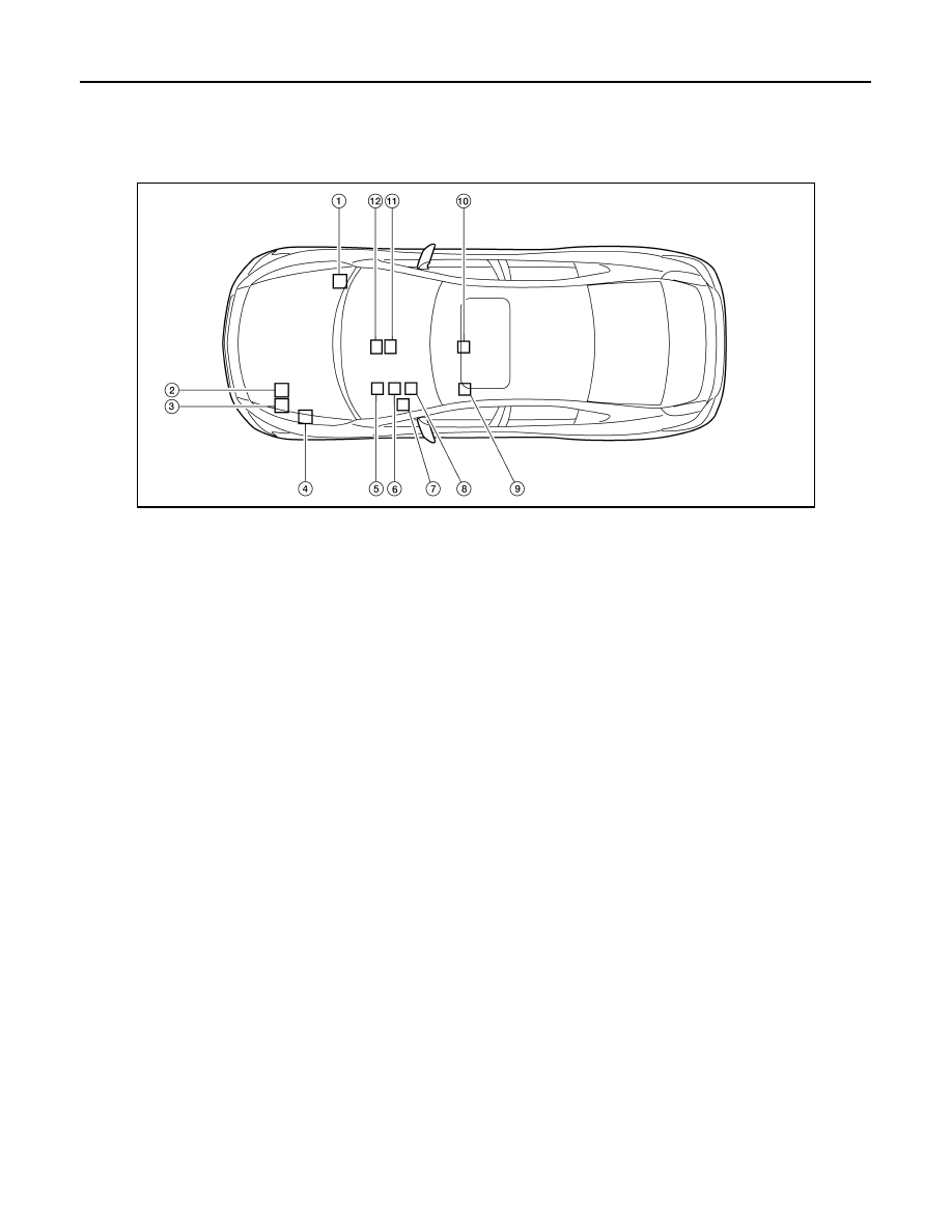
Component Parts Location

INFOID:0000000009471929

AWMIA1101ZZ

1.

ABS actuator and electric unit (con-
trol unit) E26

2.

TCM F15

3.

ECM E10

4.

IPDM E/R E17

5.

BCM M19

6.

Combination meter M24

7.

Data link connector M22

8.

Steering angle sensor M53

9.

Driver seat control unit B203

10. Air bag diagnosis sensor unit M43

11. A/C auto amp. M37

12. AV control unit

M156: With BOSE audio system - 
without navigation system
M163: With BOSE audio system - 
with navigation system
M119: With MID audio system

LAN

MALFUNCTION AREA CHART

LAN-37

< DTC/CIRCUIT DIAGNOSIS >

[CAN]

C

D

E

F

G

H

I

J

K

L

B

A

O

P

N

MALFUNCTION AREA CHART

Main Line

INFOID:0000000009471930

Branch Line

INFOID:0000000009471931

Short Circuit

INFOID:0000000009471932

Malfunction area

Reference

Main line between driver seat control unit and data link connector

LAN-38, "Diagnosis Procedure"

Main line between data link connector and A/C auto amp.

LAN-39, "Diagnosis Procedure"

Main line between A/C auto amp. and ABS actuator and electric unit (control unit)

LAN-40, "Diagnosis Procedure"

Main line between A/C auto amp. and air bag diagnosis sensor unit

LAN-41, "Diagnosis Procedure"

Main line between air bag diagnosis sensor unit and ABS actuator and electric unit 
(control unit)

LAN-42, "Diagnosis Procedure"

Malfunction area

Reference

ECM branch line circuit 

LAN-43, "Diagnosis Procedure"

Driver seat control unit branch line circuit 

LAN-44, "Diagnosis Procedure"

BCM branch line circuit 

LAN-45, "Diagnosis Procedure"

Data link connector branch line circuit 

LAN-46, "Diagnosis Procedure"

Combination meter branch line circuit

LAN-47, "Diagnosis Procedure"

AV control unit branch line circuit 

LAN-48, "Diagnosis Procedure"

A/C auto amp. branch line circuit 

LAN-49, "Diagnosis Procedure"

Steering angle sensor branch line circuit 

LAN-50, "Diagnosis Procedure"

Air bag diagnosis sensor unit branch line circuit 

LAN-51, "Diagnosis Procedure"

ABS actuator and electric unit (control unit) branch line circuit 

LAN-52, "Diagnosis Procedure"

TCM branch line circuit 

LAN-53, "Diagnosis Procedure"

IPDM E/R branch line circuit 

LAN-54, "Diagnosis Procedure"

Malfunction area

Reference

CAN communication circuit

LAN-55, "Diagnosis Procedure"

LAN-38

< DTC/CIRCUIT DIAGNOSIS >

[CAN]

MAIN LINE BETWEEN ADP AND DLC CIRCUIT

MAIN LINE BETWEEN ADP AND DLC CIRCUIT

Diagnosis Procedure

INFOID:0000000009471933

1.

CHECK CONNECTOR

1. Turn the ignition switch OFF.

2. Disconnect the battery cable from the negative terminal.

3. Check the following terminals and connectors for damage, bend and loose connection (connector side

and harness side).

-

Harness connector B1

-

Harness connector M6

Is the inspection result normal?

YES

>> GO TO 2.

NO

>> Repair the terminal and connector.

2.

CHECK HARNESS CONTINUITY (OPEN CIRCUIT)

1. Disconnect the following harness connectors.

-

Harness connectors B208 and B32

-

Harness connectors B1 and M6

2. Check the continuity between the harness connectors.

Is the inspection result normal?

YES

>> GO TO 3.

NO

>> Repair the main line between the harness connectors B32 and B1.

3.

CHECK HARNESS CONTINUITY (OPEN CIRCUIT)

Check the continuity between the harness connector and the data link connector.

Is the inspection result normal?

YES (Present error)>>Check CAN system type decision again.

YES (Past error)>>Error was detected in the main line between the driver seat control unit and the data link

connector.

NO

>> Repair the main line between the harness connector M6 and the data link connector.

Harness connector

Harness connector

Continuity

Connector No.

Terminal No.

Connector No.

Terminal No.

B32

9

B1

15J

Existed

10

16J

Existed

Harness connector

Data link connector

Continuity

Connector No.

Terminal No.

Connector No.

Terminal No.

M6

15J

M22

6

Existed

16J

14

Existed

LAN

MAIN LINE BETWEEN DLC AND HVAC CIRCUIT

LAN-39

< DTC/CIRCUIT DIAGNOSIS >

[CAN]

C

D

E

F

G

H

I

J

K

L

B

A

O

P

N

MAIN LINE BETWEEN DLC AND HVAC CIRCUIT

Diagnosis Procedure

INFOID:0000000009471934

1.

CHECK HARNESS CONTINUITY (OPEN CIRCUIT)

1. Turn the ignition switch OFF.

2. Disconnect the battery cable from the negative terminal.

3. Disconnect the following harness connectors.

-

ECM

-

A/C auto amp.

4. Check the continuity between the data link connector and the A/C auto amp. harness connector.

Is the inspection result normal?

YES (Present error)>>Check CAN system type decision again.

YES (Past error)>>Error was detected in the main line between the data link connector and the A/C auto

amp. 

NO

>> Repair the main line between the data link connector and the A/C auto amp.

Data link connector

A/C auto amp. harness connector

Continuity

Connector No.

Terminal No.

Connector No.

Terminal No.

M22

6

M37

1

Existed

14

2

Existed


Content   ..  804  805  806  807   ..