Nissan Maxima. Manual - part 797
CENTER CONSOLE ASSEMBLY
IP-21
< UNIT DISASSEMBLY AND ASSEMBLY >
C
D
E
F
G
H
I
K
L
M
A
B
IP
N
O
P
UNIT DISASSEMBLY AND ASSEMBLY
CENTER CONSOLE ASSEMBLY
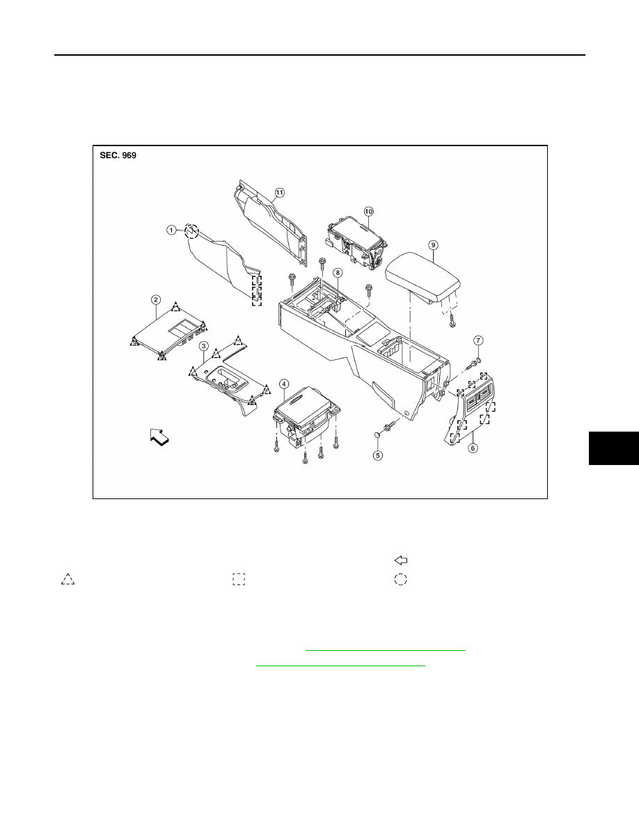
Exploded View
INFOID:0000000009465913
Disassembly and Assembly
INFOID:0000000009465914
DISASSEMBLY
1. Remove the center console assembly. Refer to
IP-14, "Removal and Installation"
2. Remove the power sockets. Refer to
PWO-7, "Removal and Installation"
.
3. Remove the center console finisher switches (if equipped), then detach the harness clips and remove the
center console harness.
4. Remove the cup holder screws and then remove the cup holder assembly.
5. Remove the center console storage bin screws and then remove the center console storage bin.
6. Remove the center console rear finisher.
7. Remove the center console lid assembly screws and remove the center console lid assembly.
ASSEMBLY
Assembly is in the reverse order of disassembly.
1.
Center console side finisher (LH)
2.
Center console finisher
3.
CVT finisher
4.
Center console storage bin
5.
Center console screw cover (LH)
6.
Center console rear finisher
7.
Center console screw cover (RH)
8.
Center console
9.
Center console lid assembly
10. Cup holder
11. Center console side finisher (RH)
Front
Clip
Metal clip
Pawl
AWJIA0542ZZ