Nissan Maxima. Manual - part 765


  Index      Nissan     Nissan Maxima (2009-2014 year) - Service and Repair Manual


Search            


Content   ..  763  764  765  766   ..


Nissan Maxima. Manual - part 765


BATTERY SAVER OUTPUT/POWER SUPPLY CIRCUIT

INL-19

< DTC/CIRCUIT DIAGNOSIS >

C

D

E

F

G

H

I

J

K

M

A

B

INL

N

O

P

BATTERY SAVER OUTPUT/POWER SUPPLY CIRCUIT

Description

INFOID:0000000009465421

Provides the interior room lamp power supply. Also cuts the power supply when the interior room lamp battery

saver is activated.

Component Function Check

INFOID:0000000009465422

1.

CHECK BATTERY SAVER OUTPUT/POWER SUPPLY FUNCTION

CONSULT

1. Turn ignition switch ON.

2. Turn each interior room lamp ON.

-

Front room/map lamp assembly

-

Personal lamps rear

-

Foot lamps

-

Front step lamps

-

Rear step lamps

-

Trunk room lamp

-

Vanity mirror lamps

3. Select “BATTERY SAVER” of BCM (BATTERY SAVER) active test item.

4.  While operating the test item, check that each interior room lamp turns ON/OFF.

Is the inspection result normal?

YES

>> Battery saver output/power supply circuit is normal.

NO

>> Refer to 

INL-19, "Diagnosis Procedure"

.

Diagnosis Procedure

INFOID:0000000009465423

Regarding Wiring Diagram information, refer to 

INL-55, "Wiring Diagram"

.

1.

CHECK BATTERY SAVER OUTPUT/POWER SUPPLY OUTPUT

CONSULT

1. Turn ignition switch ON.

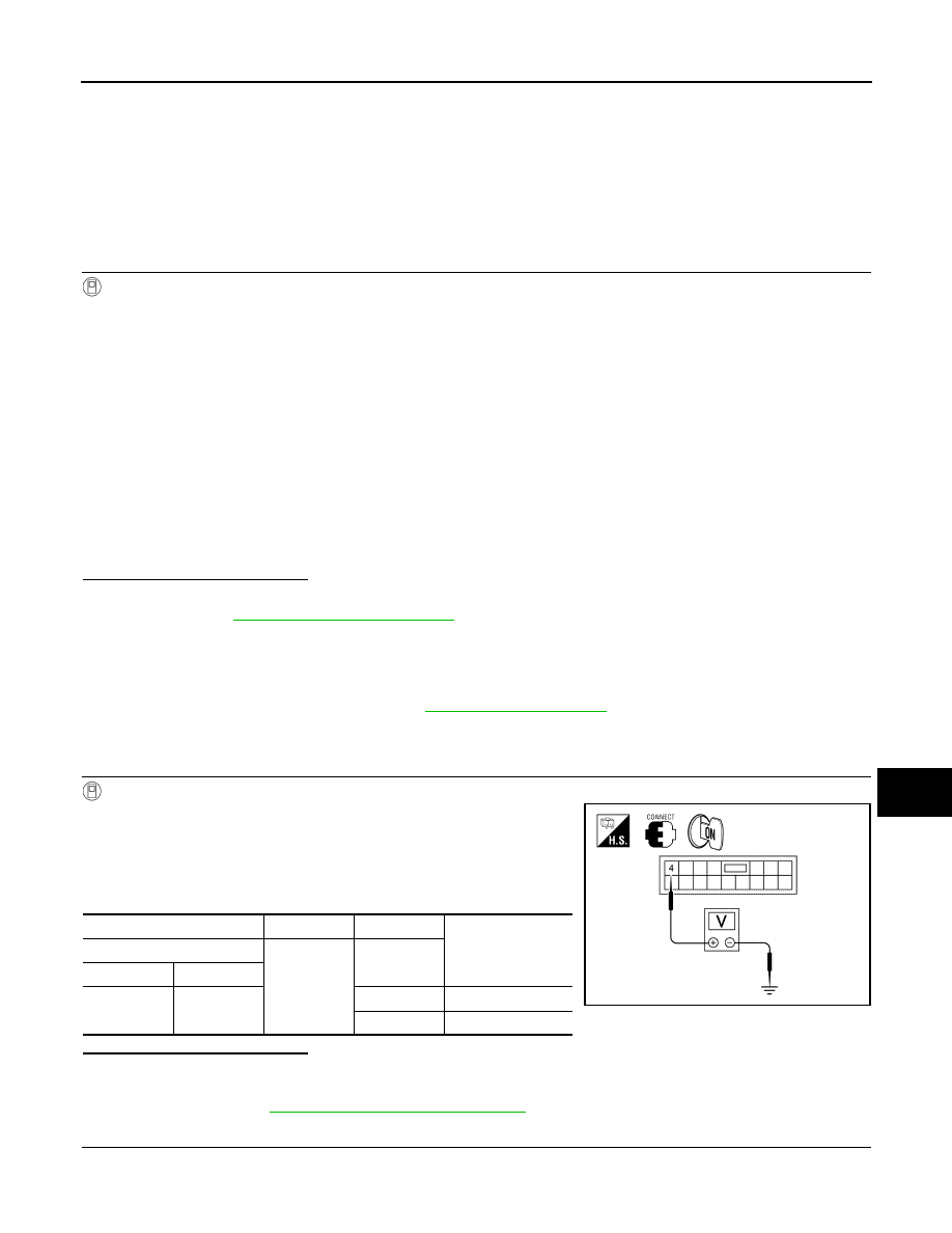
2. Select “BATTERY SAVER” of BCM (BATTERY SAVER) active

test item.

3. While operating the test item, check voltage between BCM con-

nector M17 terminal 4 and ground.

Is the inspection result normal?

YES

>> GO TO 2

NO

>> Replace BCM after making sure battery saver output/power supply circuit is not shorted to volt-

age. Refer to 

BCS-79, "Removal and Installation"

.

2.

CHECK BATTERY SAVER OUTPUT/POWER SUPPLY OPEN CIRCUIT

1. Turn ignition switch OFF.

2. Disconnect the following connectors.

OFF

: Interior room lamp OFF

ON

: Interior room lamp ON

(+)

(-)

Test item

Voltage

BCM

Ground

BATTERY 

SAVER

Connector

Terminal

M17

4

OFF

0V

ON

Battery voltage

ALLIA0102ZZ

INL-20

< DTC/CIRCUIT DIAGNOSIS >

BATTERY SAVER OUTPUT/POWER SUPPLY CIRCUIT

-

BCM  M17

-

Front room/map lamp assembly

-

Vanity mirror lamp LH

-

Vanity mirror lamp RH

-

Foot lamp LH

-

Foot lamp RH

-

Front step lamp LH

-

Front step lamp RH

-

Rear step lamp LH

-

Rear step lamp RH

-

Trunk room lamp

3. Check continuity between BCM connector M17 terminal 4 and each interior room lamp connector.

Is the inspection result normal?

YES

>> GO TO 3

NO

>> Repair the harness or connectors.

3.

CHECK BATTERY SAVER OUTPUT/POWER SUPPLY SHORT CIRCUIT

Check continuity between BCM connector M17 terminal 4 and

ground.

Is the inspection result normal?

YES

>> Replace the interior room lamp. Refer to 

INL-84,

"Removal and Installation"

.

NO

>> Repair the harness or connectors.

BCM

Each interior room lamp

Continuity

Connector

Terminal

Connector

Terminal

M17

4

Front room/map lamp assembly

R8

1

Yes

Vanity mirror lamp LH

R3

2

Vanity mirror lamp RH

R9

2

Foot lamp LH

M99

1

Foot lamp RH

M100

1

Front step lamp LH

D11

1

Front step lamp RH

D109

1

Rear step lamp LH

D206

1

Rear step lamp RH

D301

1

Trunk room lamp

B36

1

BCM

Ground

Continuity

Connector

Terminal

M17

4

No

ALLIA0103ZZ

INTERIOR ROOM LAMP CONTROL CIRCUIT

INL-21

< DTC/CIRCUIT DIAGNOSIS >

C

D

E

F

G

H

I

J

K

M

A

B

INL

N

O

P

INTERIOR ROOM LAMP CONTROL CIRCUIT

Description

INFOID:0000000009465424

Controls each interior room lamp (ground side) by PWM signal.

NOTE:

PWM signal control period is approximately 250 Hz (in the gradual brightening/dimming).

Component Function Check

INFOID:0000000009465425

CAUTION:

 Before performing the diagnosis, check that the following is normal.

• Battery saver output/power supply

• Front room/map lamp assembly bulbs

• Personal lamp rear bulbs

• Foot lamp bulbs

1.

CHECK INTERIOR ROOM LAMP CONTROL FUNCTION

CONSULT

1. Switch the front room/map lamp assembly to DOOR.

2. Turn ignition switch ON.

3. Select “INT LAMP” of BCM (INT LAMP) active test item.

4. While operating the test item, check that each interior room lamp turns ON/OFF (gradual brightening/dim-

ming).

Is the inspection result normal?

YES

>> Interior room lamp control circuit is normal.

NO

>> Refer to 

INL-21, "Diagnosis Procedure"

.

Diagnosis Procedure

INFOID:0000000009465426

Regarding Wiring Diagram information, refer to 

INL-55, "Wiring Diagram"

.

1.

CHECK INTERIOR ROOM LAMP CONTROL OUTPUT

CONSULT

1. Turn ignition switch ON.

2. Select “INT LAMP” of BCM (INT LAMP) active test item.

3. While operating the test item, check voltage between BCM connector M17 terminal 19 and ground.

Is the inspection result normal?

YES

>> Interior room lamp control circuit is operating normally.

Fixed ON>>GO TO 3

Fixed OFF>>GO TO 2

2.

CHECK INTERIOR ROOM LAMP CONTROL OPEN CIRCUIT

1. Turn ignition switch OFF.

2. Disconnect BCM connector M17, front room/map lamp assembly and foot lamp connectors.

3. Check continuity between BCM connector M17 terminal 19 and each interior room lamp connector.

ON

: Interior room lamp gradual brightening

OFF

: Interior room lamp gradual dimming

BCM

Ground

Test item

Voltage

Connector

Terminal

INT LAMP

M17

19

ON

0V

OFF

Battery voltage

INL-22

< DTC/CIRCUIT DIAGNOSIS >

INTERIOR ROOM LAMP CONTROL CIRCUIT

Is the inspection result normal?

YES

>> Check interior room lamps for an open. If OK, replace BCM. Refer to 

BCS-79, "Removal and

Installation"

If NG, replace the interior room lamp. Refer to 

INL-84, "Removal and Installation"

.

NO

>> Repair the harness or connectors.

3.

CHECK INTERIOR ROOM LAMP CONTROL SHORT CIRCUIT

1. Turn ignition switch OFF.

2. Disconnect BCM connector M17, front room/map lamp assem-

bly and foot lamp connectors.

3. Check continuity between BCM connector M17 terminal 19 and

ground.

Is the inspection result normal?

YES

>> Check interior room lamps for a short circuit. If OK, replace BCM. Refer to 

BCS-79, "Removal and

Installation"

If NG, replace the interior room lamp. Refer to 

INL-84, "Removal and Installation"

.

NO

>> Repair the harness or connectors.

BCM

Interior room lamp

Continuity

Connector

Terminal

Connector

Terminal

M17

19

Front room/map lamp assembly

R8

2

Yes

Foot lamp LH

M99

2

Foot lamp RH

M100

2

BCM

Ground

Continuity

Connector

Terminal

M17

19

No

ALLIA0105ZZ


Content   ..  763  764  765  766   ..