Nissan Maxima. Manual - part 747
HAC-164
< DTC/CIRCUIT DIAGNOSIS >
[WITH MONOCHROME DISPLAY]
A/C SWITCH ASSEMBLY SIGNAL CIRCUIT
A/C SWITCH ASSEMBLY SIGNAL CIRCUIT
Diagnosis Procedure
INFOID:0000000010051167
Regarding Wiring Diagram information, refer to
HAC-173, "Wiring Diagram - With Monochrome Display"
1.
CHECK WITH SELF-DIAGNOSIS FUNCTION OF CONSULT
1. Using CONSULT, perform “SELF-DIAGNOSIS RESULTS” of HVAC.
2. Check if any DTC No. is displayed in the self-diagnosis results.
NOTE:
If DTC is displayed along with DTC U1000 or U1010, first diagnose the DTC U1000 or U1010. Refer to
Is any DTC No. displayed?
YES
>> Perform diagnosis for the applicable DTC. Refer to
NO
>> GO TO 2.
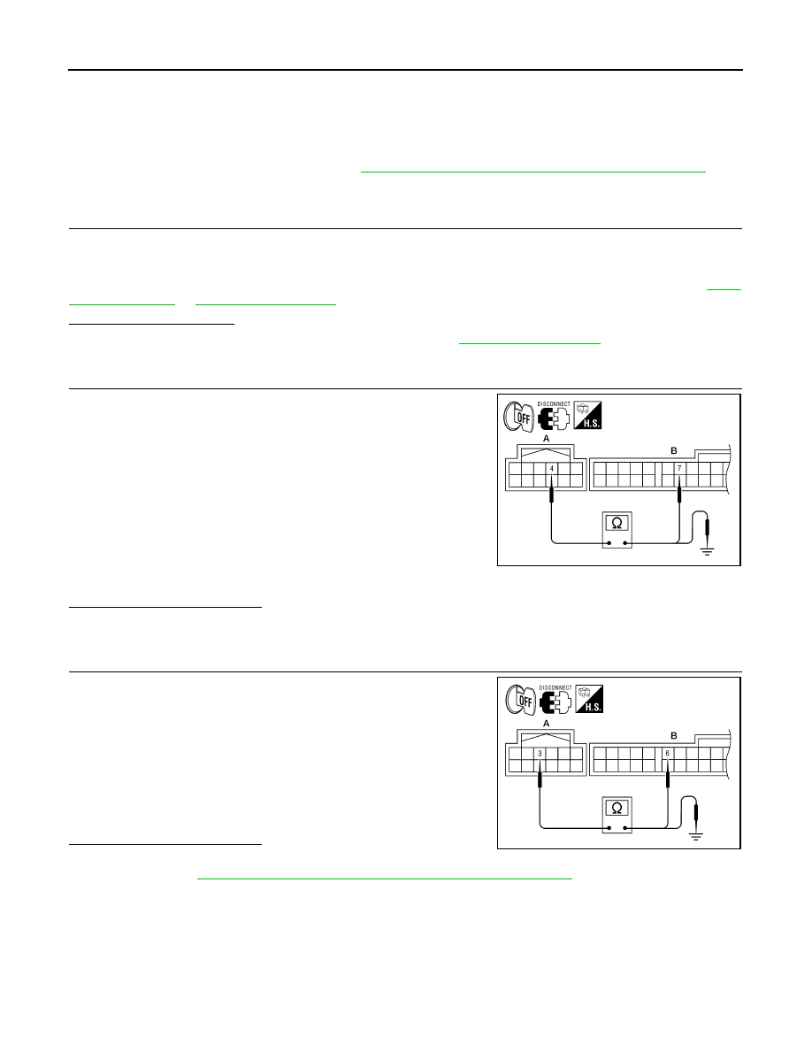
2.
CHECK RX (A/C SWITCH ASSEMBLY
→ A/C AUTO AMP.) CIRCUIT CONTINUITY
1. Turn ignition switch OFF.
2. Disconnect the A/C switch assembly and the A/C auto amp.
connectors.
3. Check continuity between A/C switch assembly harness con-
nector M104 (A) terminal 4 and A/C auto amp. harness connec-
tor M37 (B) terminal 7.
4. Check continuity between A/C switch assembly harness con-
nector M104 (A) terminal 4 and ground.
Is the inspection result normal?
YES
>> GO TO 3.
NO
>> Repair harness or connector.
3.
CHECK TX (A/C AUTO AMP.
→ A/C SWITCH ASSEMBLY) CIRCUIT CONTINUITY
1. Check continuity between A/C switch assembly harness con-
nector M104 (A) terminal 3 and A/C auto amp. harness connec-
tor M37 (B) terminal 6.
2. Check continuity between A/C switch assembly harness con-
nector M104 (A) terminal 3 and ground.
Is the inspection result normal?
YES
>> Perform trouble diagnosis for the A/C switch assembly.
HAC-166, "A/C SWITCH ASSEMBLY : Diagnosis Procedure"
.
NO
>> Repair harness or connector.
4 - 7
: Continuity should exist.
4 - Ground
: Continuity should not exist.
AWIIA1177ZZ
3 - 6
: Continuity should exist.
3 - Ground
: Continuity should not exist.
AWIIA1178ZZ