Nissan Maxima. Manual - part 737


  Index      Nissan     Nissan Maxima (2009-2014 year) - Service and Repair Manual


Search            


Content   ..  735  736  737  738   ..


Nissan Maxima. Manual - part 737


HAC-124

< SYSTEM DESCRIPTION >

[WITH MONOCHROME DISPLAY]

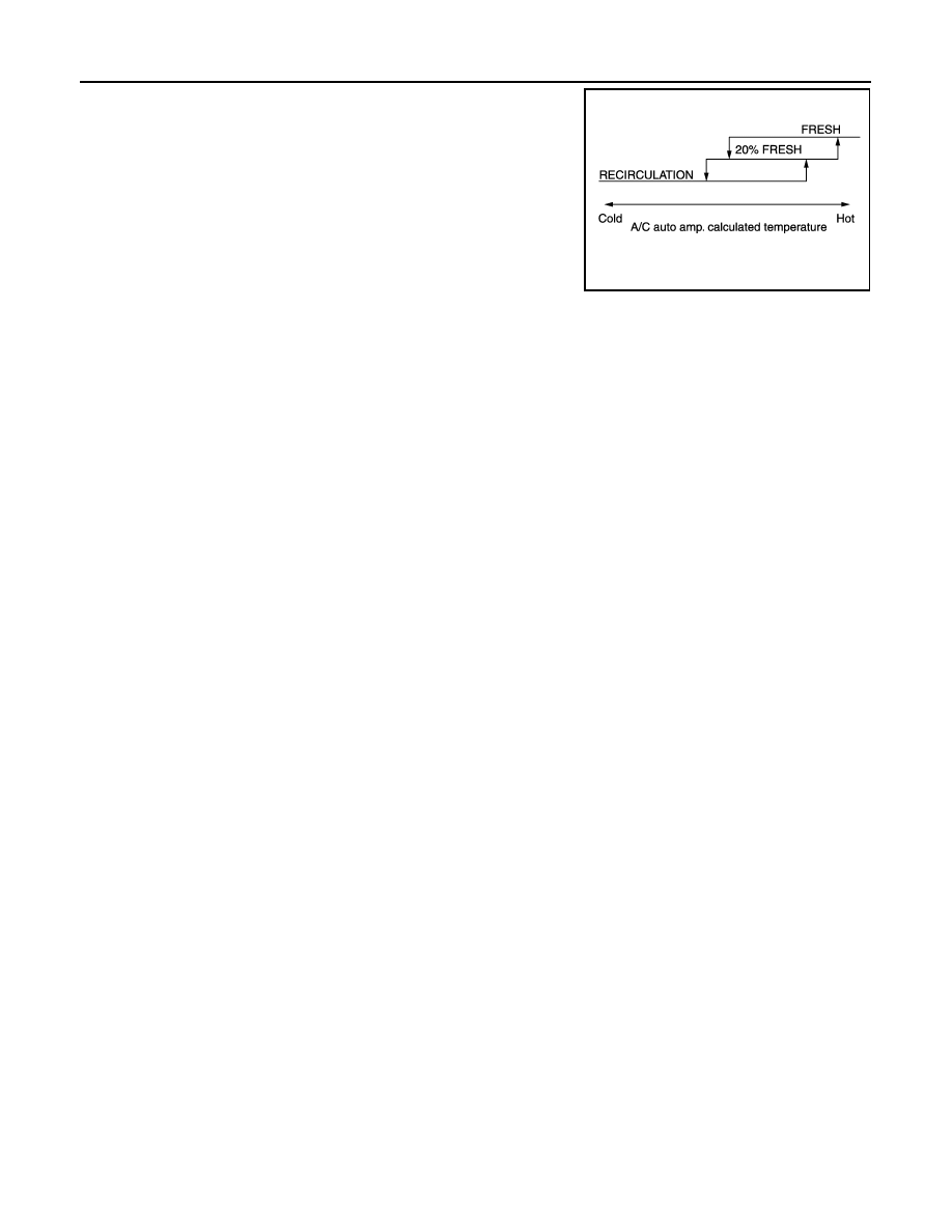
INTAKE DOOR CONTROL SYSTEM

Intake Door Control Specification

JPIIA0634GB

BLOWER MOTOR CONTROL SYSTEM

HAC-125

< SYSTEM DESCRIPTION >

[WITH MONOCHROME DISPLAY]

C

D

E

F

G

H

J

K

L

M

A

B

HAC

N

O

P

BLOWER MOTOR CONTROL SYSTEM

System Diagram

INFOID:0000000010051121

System Description

INFOID:0000000010051122

Fan speed is automatically controlled by the temperature setting, ambient temperature, in-vehicle tempera-

ture, intake temperature, amount of sunload and air mix door position.

By pressing the AUTO switch, the blower motor starts to gradually increase airflow volume.

When engine coolant temperature is low, the blower motor operation is delayed to prevent cool air from flow-

ing.

SYSTEM OPERATION

System Operation

• For airflow, the manual selection (1-7) with the fan control dial has

priority. 

• If the AUTO switch is pressed or if the DEF switch is pressed while

in the OFF condition, it changes to the automatic control by A/C

auto amp. 

• When increasing the airflow, it changes the duty ratio of the blower

motor drive signal to prevent the airflow from suddenly increasing. 

• There are the following types of airflow control: starting airflow con-

trol, starting airflow control at low coolant temperature, starting air-

flow control at high in-vehicle temperature, and airflow control at

actuator operation in addition to manual control, normal automatic

airflow control. 

Normal Automatic Airflow Control

• When the target temperature is set by the temperature control switch of A/C switch assembly, the A/C auto

amp. performs the calculation and decides the target according to the signal from each sensor. 

• The A/C auto amp. changes the duty ratio of blower motor drive signal and controls the airflow, continuously,

so that the airflow becomes the target airflow. 

• The minimum airflow will change, according to the sunload, when the air discharge outlet is VENT or B/L. 

AWIIA1117GB

AWIIA1094GB

HAC-126

< SYSTEM DESCRIPTION >

[WITH MONOCHROME DISPLAY]

BLOWER MOTOR CONTROL SYSTEM

Fan Speed Control Specification

Starting Airflow Control

• When starting the automatic control of airflow, the system gradually increases the duty ratio of the blower

motor drive signal to prevent too much air from blowing. 

• The time period from when the airflow changes from LO to HI is approximately 8 seconds. 

• It becomes the starting airflow control at low coolant temperature according to the calculation result of the A/

C auto amp. and engine coolant temperature [approximately 56

°C (133°F) or less] during the automatic air-

flow control. 

• Do not perform the starting airflow control when the air discharge outlet is set to DEF. 

Starting Fan Speed Control

Start-up from COLD SOAK Condition (Automatic mode)

In cold start-up condition, where the engine coolant temperature is below 56

°C (133°F), the blower does not

operate for a short period of time (up to 150 seconds). The exact start delay time varies depending on the

ambient temperature and engine coolant temperature.

In the most extreme case (very low ambient temperature) the blower start delay is 150 seconds, as described

above. After this delay, the blower will operate at low speed until the engine coolant temperature rises above

56

°C (133°F), and then the fan speed increases to the objective speed.

Start-up from usual or HOT SOAK Condition (Automatic mode)

The blower will begin operation momentarily after the AUTO switch is pressed. The fan speed rises gradually

to the objective speed over a time period of 3 seconds or less (actual time depends on the objective fan

speed).

JPIIA0635GB

MAGNET CLUTCH CONTROL SYSTEM

HAC-127

< SYSTEM DESCRIPTION >

[WITH MONOCHROME DISPLAY]

C

D

E

F

G

H

J

K

L

M

A

B

HAC

N

O

P

MAGNET CLUTCH CONTROL SYSTEM

System Diagram

INFOID:0000000010051123

System Description

INFOID:0000000010051124

The A/C auto amp. controls A/C compressor operation by ambient temperature, intake air temperature and

signal from ECM.

SYSTEM OPERATION

When the A/C switch, the AUTO switch, or the DEF switch is pressed, or when shifting mode position to D/F,

the A/C auto amp. transmits the A/C switch signal and blower fan motor switch signal to the ECM, via CAN

communication.

ECM judges whether the A/C compressor can be turned ON, based on each sensor status (refrigerant-pres-

sure sensor signal, throttle angle, etc.). If the ECM judges that the A/C compressor can be turned ON, it sends

A/C compressor request signal to the IPDM E/R, via CAN communication.

Upon receipt of A/C compressor request signal from the ECM, the IPDM E/R turns the A/C relay ON to oper-

ate the A/C compressor.

When sending A/C compressor request signal to the IPDM E/R via CAN communication line, the ECM simul-

taneously sends A/C compressor feedback signal to A/C auto amp. via CAN communication line.

The ECM sends A/C compressor feedback signal to A/C auto amp., then, uses input A/C compressor feed-

back signal to control air inlet.

A/C compressor Protection Control

The ECM makes the A/C relay turn OFF and stops the A/C compressor when pressure on the high-pressure
side, detected by the refrigerant pressure sensor, is over approximately 3,119 kPa (31.8 kg/cm

2

, 452 psi), or

below approximately 118 kPa (1.2 kg/cm

2

, 17 psi).

Low Temperature Protection Control

Turn the A/C relay to OFF and stop the A/C compressor by the signal from the A/C auto amp., according to the

evaporator passing air temperature detected by the intake sensor and the ambient temperature detected by

the ambient sensor. 

JPIIA0505GB


Content   ..  735  736  737  738   ..