Nissan Maxima. Manual - part 703


  Index      Nissan     Nissan Maxima (2009-2014 year) - Service and Repair Manual


Search            


Content   ..  701  702  703  704   ..


Nissan Maxima. Manual - part 703


HA-38

< REMOVAL AND INSTALLATION >

COMPRESSOR

16. Remove the RH compressor bolts.
17. Remove the front compressor bolts using a power tool.
18. Disconnect the compressor wire harness clip from the compressor.
19. Remove the compressor.

INSTALLATION

Installation is in the reverse order of removal.

CAUTION:

• For installation, tighten the compressor bolts in the order as shown.

• Do not reuse O-rings.

• Apply A/C oil to the O-rings of the low-pressure flexible hose and high-pressure flexible hose for

installation.

• After charging the A/C refrigerant, check for leaks. Refer to 

HA-33, "Inspection"

.

Removal and Installation for Compressor Clutch

INFOID:0000000009465945

NOTE:

Illustrations shown with the compressor out of the vehicle are for clarity, it is not necessary to remove the com-

pressor.

REMOVAL

1. Remove the front wheel and tire (RH). Refer to 

WT-60, "Adjustment"

.

2. Remove the engine under cover. Refer to 

EXT-15, "Exploded View"

.

3. Release the drive belt from the A/C pulley. Refer to 

EM-14, "Removal and Installation"

.

4. Reposition the power steering line aside, do not disconnect the power steering line.
5. Remove the center bolt by holding the clutch disc steady using a suitable tool.
6. Remove the clutch disc and shims.

CAUTION:

Retain all the shims for installation.
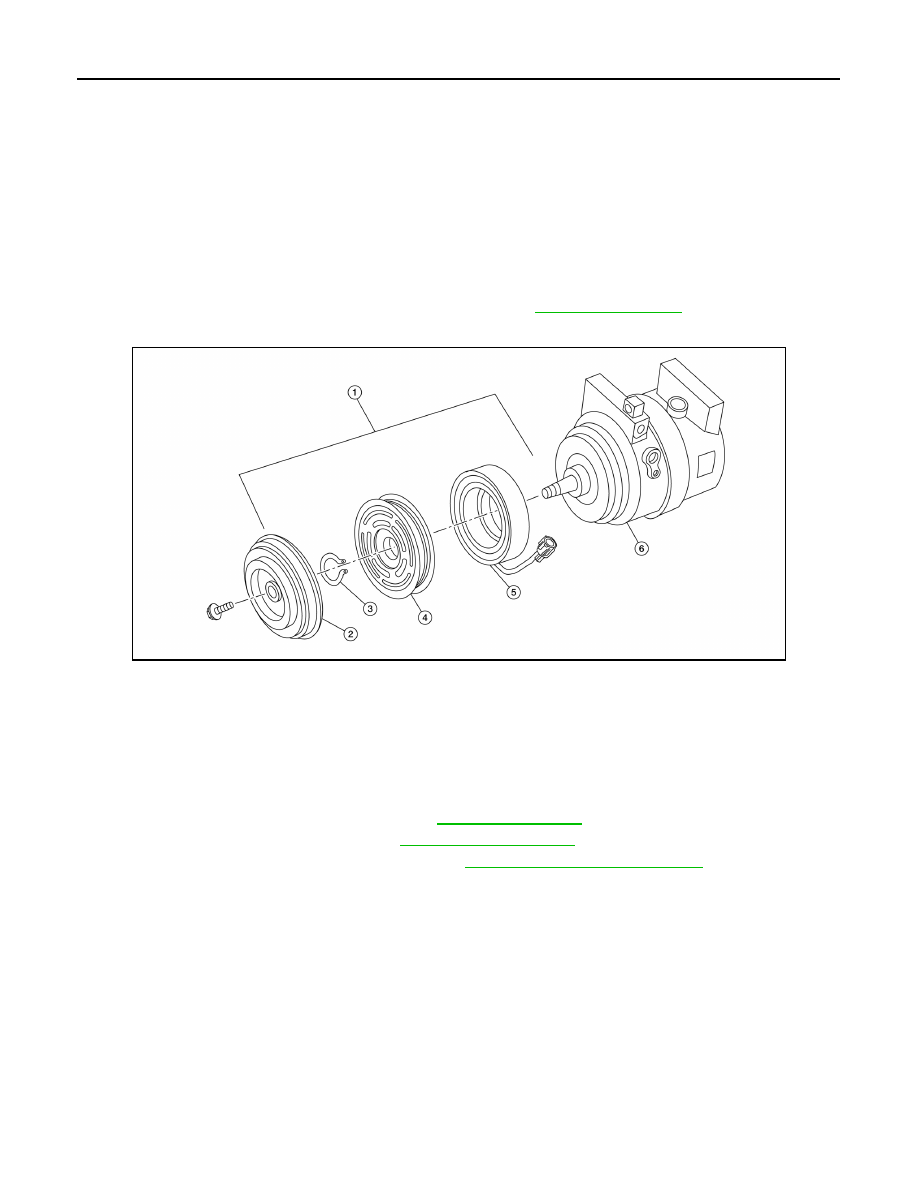
ALIIA0487ZZ

1.

Magnetic clutch assembly

2.

Clutch disk

3.

Snap ring

4.

Pulley

5.

Magnet coil

6.

Compressor

COMPRESSOR

HA-39

< REMOVAL AND INSTALLATION >

C

D

E

F

G

H

J

K

L

M

A

B

HA

N

O

P

7. Remove the snap ring using a suitable tool as shown.

8. Remove the pulley assembly using a suitable tool (A) as shown.

CAUTION:

• To prevent deformation of the pulley groove, the puller

claws should be hooked under (not into) the pulley

groove.

9. Disconnect the magnet coil harness.
10. Remove the three magnet coil screws using a suitable tool as

shown, then remove the magnet coil.

INSPECTION AFTER REMOVAL

• Shim  (1)

• Snap ring (2)

• Clutch disc (3)

• Pulley (4)

• Magnet coil (5)

• Center bolt (A)

• Magnet coil screws (B)

Clutch Disc

If the contact surface shows signs of damage due to excessive heat, replace the clutch disc and pulley.

Pulley

Check the appearance of the pulley assembly. If the contact surface of the pulley shows signs of excessive

grooving, replace the clutch disc and pulley. The contact surfaces of the pulley assembly should be cleaned

with a suitable solvent before installation.

Magnet Coil

Check the magnet coil for a loose connection or cracked insulation. Replace as necessary.

RHA072C

AWIIA1285ZZ

WHA212

WJIA2296E

HA-40

< REMOVAL AND INSTALLATION >

COMPRESSOR

INSTALLATION

1. Install the magnet coil by aligning the magnet coil pin (A) with

the hole (B) in the compressor front head as shown, then install

the magnet coil screws.

: Front

CAUTION:

• Be sure to align the magnet coil pin with the hole in the

compressor front head.

2. Connect the magnet coil harness.
3. Install the pulley assembly using Tool and a wrench as shown,

then install the snap ring using a suitable tool.

4. Install the clutch disc (1) on the drive shaft, together with all of

the original shim(s) (2) using a suitable tool (A).

5. Install the center bolt using suitable tool.

• After tightening the center bolt to specification, check that the pulley rotates smoothly.

6. Reposition the power steering line back into position, do not disconnect the power steering line.
7. Install the drive belt back onto the A/C pulley. Refer to 

EM-14, "Removal and Installation"

.

8. Install the engine under cover. Refer to 

EXT-15, "Exploded View"

.

9. Install the front wheel and tire (RH). Refer to 

WT-60, "Adjustment"

.

INSPECTION AFTER INSTALLATION

ALIIA0389ZZ

Tool number

: — (J-38873-A)

WJIA1016E

WJIA2297E

Center bolt

: 12 N·m (1.2 kg-m, 9 ft-lb)

COMPRESSOR

HA-41

< REMOVAL AND INSTALLATION >

C

D

E

F

G

H

J

K

L

M

A

B

HA

N

O

P

Check the clearance (B) all the way around between the clutch disc

(1) and pulley (2) using a suitable tool (A) as shown.

If the specified clearance (B) is not obtained, replace the adjusting

shim(s) and recheck the clearance (B) as shown.

BREAK-IN OPERATION

When replacing compressor clutch assembly, always conduct the break-in operation. This is done by engag-

ing and disengaging the clutch about 30 times. Break-in operation raises the level of transmitted torque.

Clutch disc-to-pulley clearance (B)

: 0.3 - 0.6 mm 
(0.012 - 0.024 in)

WJIA2298E


Content   ..  701  702  703  704   ..