Nissan Maxima. Manual - part 671
FRONT SUSPENSION ASSEMBLY
FSU-13
< UNIT REMOVAL AND INSTALLATION >
C
D
F
G
H
I
J
K
L
M
A
B
FSU
N
O
P
UNIT REMOVAL AND INSTALLATION
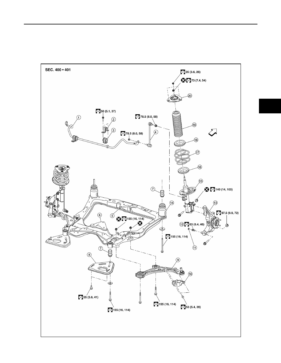
FRONT SUSPENSION ASSEMBLY
Exploded View
INFOID:0000000009466799
AWEIA0269ZZ
|
|
|
FRONT SUSPENSION ASSEMBLY FSU-13 < UNIT REMOVAL AND INSTALLATION > C D F G H I J K L M A B FSU N O P UNIT REMOVAL AND INSTALLATION FRONT SUSPENSION ASSEMBLY Exploded View INFOID:0000000009466799 AWEIA0269ZZ |