Nissan Maxima. Manual - part 577


  Index      Nissan     Nissan Maxima (2009-2014 year) - Service and Repair Manual


Search            


Content   ..  575  576  577  578   ..


Nissan Maxima. Manual - part 577


EXL-50

< DTC/CIRCUIT DIAGNOSIS >

[XENON TYPE]

TURN SIGNAL LAMP CIRCUIT

5. With turn signal switch operating, check the voltage between the rear combination lamp harness connec-

tor and ground.

6. With turn signal switch operating, check the voltage between the door mirror (if equipped with turn signals

in the mirrors) harness connector and ground.

Is the measurement value normal?

YES

>> GO TO 5.

NO

>> GO TO 3.

3.

CHECK TURN SIGNAL LAMP CIRCUIT FOR OPEN 

1. Turn ignition switch OFF.

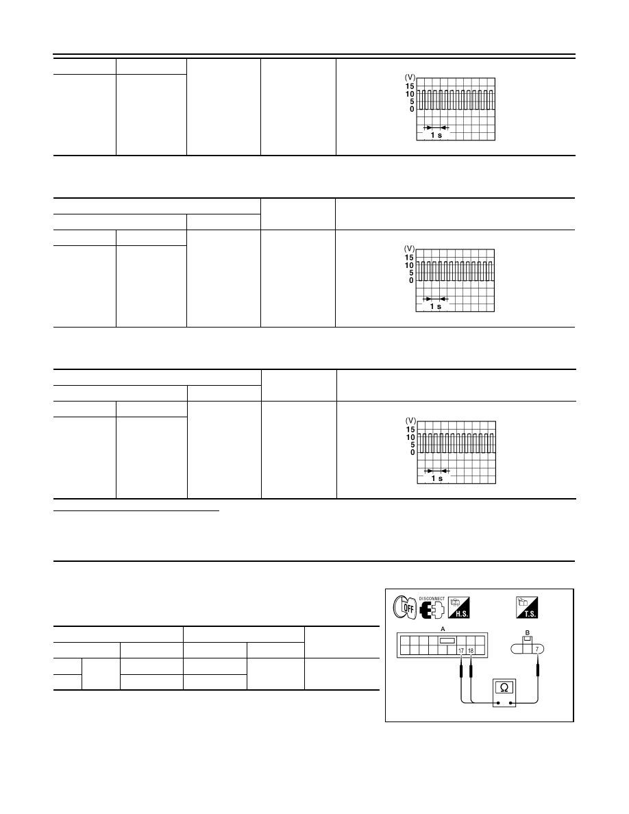
2. Disconnect BCM connector M17.

3. Check continuity between the BCM harness connector (A) and

the front combination lamp connector (B).

E217

LH

7

Ground

E224

RH

PKID0926E

(+)

(

−)

Voltage

Connector

Terminal

B30

LH

6

Ground

B45

RH

PKID0926E

(+)

(

−)

Voltage

Connector

Terminal

D4

LH

8

Ground

D107

RH

PKID0926E

A

B

Continuity

Connector

Terminal

Connector

Terminal

 LH

M17

18

E217

7

Yes

 RH

17

E224

AWLIA1653ZZ

TURN SIGNAL LAMP CIRCUIT

EXL-51

< DTC/CIRCUIT DIAGNOSIS >

[XENON TYPE]

C

D

E

F

G

H

I

J

K

M

A

B

EXL

N

O

P

4. Check continuity between the BCM harness connector (A) and

the rear combination lamp harness connector (B).

5. Check continuity between the BCM harness connector (A) and

the door mirror connector (B) (if equipped with turn signal in mir-

ror).

Does continuity exist?

YES

>> GO TO 4.

NO

>> Repair the harnesses or connectors.

4.

CHECK TURN SIGNAL LAMP SHORT CIRCUIT

Check continuity between the BCM harness connector and ground.

Does continuity exist?

YES

>> Repair the harnesses or connectors.

NO

>> Replace BCM. Refer to 

PCS-35, "Removal and Installa-

tion"

.

5.

CHECK TURN SIGNAL LAMP GROUND CIRCUIT

1. Turn ignition switch OFF.

2. Check continuity between the front combination lamp and

ground.

A

B

Continuity

Connector

Terminal

Connector

Terminal

 LH

M17

18

B30

6

Yes

 RH

17

B45

AWLIA1654ZZ

A

B

Continuity

Connector

Terminal

Connector

Terminal

 LH

M17

18

D4

8

Yes

 RH

17

D107

AWLIA1655ZZ

Connector

Terminal

Continuity

LH

M17

18

Ground

No

RH

17

ALLIA0129ZZ

Connector

Terminal

Continuity

LH

E217

6

Ground

Yes

RH

E224

AWLIA1656ZZ

EXL-52

< DTC/CIRCUIT DIAGNOSIS >

[XENON TYPE]

TURN SIGNAL LAMP CIRCUIT

3. Check continuity between the rear combination lamp and

ground.

4. Check continuity between the door mirror and ground (if equipped with turn signal in mirror).

Does continuity exist?

YES

>> Replace the front combination lamp. Refer to 

EXL-154, "Removal and Installation"

the rear com-

bination lamp. Refer to 

EXL-162, "Removal and Installation"

 or door mirror (if equipped with turn

signal in mirror) . Refer to 

EXL-159, "Removal and Installation"

.

NO

>> Repair the harnesses or connectors.

Connector

Terminal

Continuity

LH

B30

4

Ground

Yes

RH

B45

AWLIA1657ZZ

Connector

Terminal

Continuity

LH

D4

7

Ground

Yes

RH

D107

OPTICAL SENSOR

EXL-53

< DTC/CIRCUIT DIAGNOSIS >

[XENON TYPE]

C

D

E

F

G

H

I

J

K

M

A

B

EXL

N

O

P

OPTICAL SENSOR

Description

INFOID:0000000010050233

The optical sensor converts the outside brightness (lux) to voltage and transmits the optical sensor signal to

the BCM.

Component Function Check

INFOID:0000000010050234

1.

CHECK OPTICAL SENSOR SIGNAL BY CONSULT

CONSULT

1. Turn the ignition switch ON.

2. Select “OPTICAL SENSOR” of BCM (HEAD LAMP) DATA MONITOR item.

3. Turn the lighting switch to AUTO.

4. While the auto light system is operating, check the monitor status. 

*: Illuminates the optical sensor. The value may be less than the standard value if brightness is weak.

Is the item status normal?

YES

>> Optical sensor is normal.

NO

>> Refer to 

EXL-53, "Diagnosis Procedure"

.

Diagnosis Procedure

INFOID:0000000010050235

Regarding Wiring Diagram information, refer to 

EXL-106, "Wiring Diagram"

.

1.

CHECK OPTICAL SENSOR POWER SUPPLY INPUT

1. Turn the ignition switch ON.

2. Turn the lighting switch to AUTO.

3. Check the voltage between the optical sensor harness connec-

tor and ground.

Is the voltage reading as specified?

YES

>> GO TO 2.

NO

>> GO TO 4.

2.

CHECK OPTICAL SENSOR GROUND INPUT

Check the voltage between the optical sensor harness connector

and ground.

Is the voltage reading as specified?

YES

>> GO TO 3.

NO

>> GO TO 6.

Monitor item

Condition

Voltage

OPTICAL SENSOR

When illuminating

3.1V or more *

When shutting off light

0.6V or less

(+)

(

−)

Voltage

Connector

Terminal

M66

1

Ground

5V

ALLIA0130ZZ

(+)

(

−)

Voltage

Connector

Terminal

M66

3

Ground

 Less than 0.2V

ALLIA0131ZZ


Content   ..  575  576  577  578   ..